What an Anti-Misalignment Idler Does
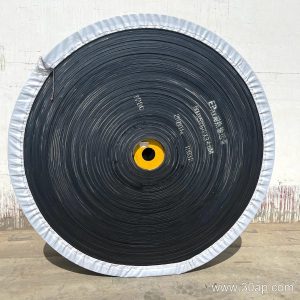
An anti-misalignment idler is a self-correcting carrying or return roller designed to bring a drifting conveyor belt back toward the center line. When a belt wanders, friction between the belt edge and the roller causes the assembly to pivot slightly, and that small rotation steers the belt back on track. On a quarry face, a coal yard, or a cement plant feed line, this kind of correction reduces edge wear and keeps material from spilling off the belt.
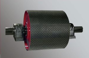
The product is also called a self-aligning idler or training idler. It sits in the troughing run or the return run and works alongside standard carrying rollers, return rollers, and a conveyor pulley at the head or tail of the line.
Construction and Tracking Principle
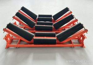
Most designs use a pair of rollers set in a swivel frame that is mounted on a vertical pivot. A small forward lean of about 1.5 to 2 degrees is often incorporated so the rotating surface guides the belt inward. Two common variants exist:
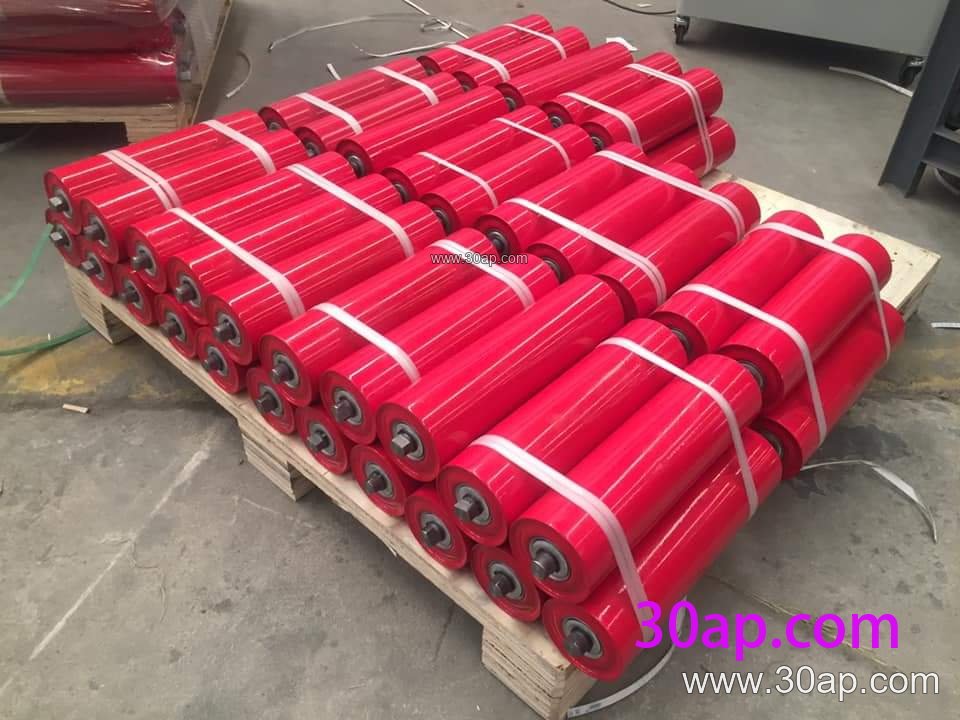
- Friction self-aligning idler – a vertical friction roller touches the belt edge and turns the frame when the belt drifts.
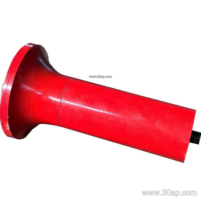
- Tapered self-aligning idler – conical or tapered ends create differential surface speed that helps the belt center itself.
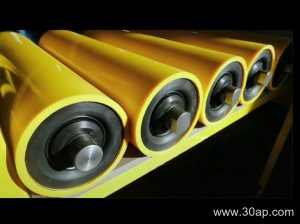
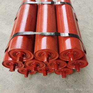
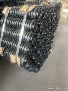
The roller shell is usually steel tube, sometimes with nylon, ceramic, or rubber ring surfaces. Bearings such as 6204, 6205, 6305, 6308, or 6310 are common, matched to load and shaft design rather than to a single roller diameter. Seals should suit dusty or wet conditions found in mining, power plant coal handling, and aggregate operations.
Where It Fits on the Conveyor
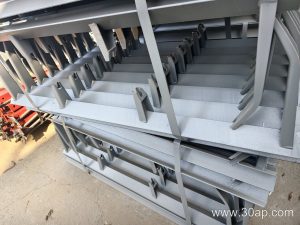
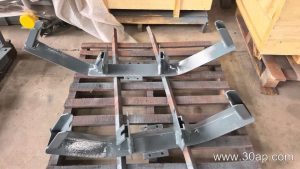
Install self-aligning units at intervals along the carrying side, often after the loading point and before the bend pulley, and on the return side where the belt is prone to wander. They are not a substitute for a drive pulley, a tail pulley, or a bend pulley; those components transmit power or change belt direction, while the anti-misalignment idler only corrects lateral position. Properly aligned conveyor brackets and a level frame are still required for the unit to work.
Typical industries include limestone mines, iron ore plants, washed coal plants, sand and gravel lines, crushing and screening circuits, and port bulk terminals.
Common Reference Dimensions
The table below gives indicative values for orientation only. Roller length changes with belt width, trough angle, and roller set form, and side rollers may differ from the center roller.
| Belt width | Common roller length (three-roll trough set) | Roller diameter range | Trough angle |
|---|---|---|---|
| B500 | approx. 200 mm | Ø63 to Ø108 | 20°, 30°, 35° |
| B650 | approx. 250 mm | Ø76 to Ø133 | 20°, 30°, 35° |
| B800 | approx. 315 mm | Ø89 to Ø133 | 20°, 30°, 35°, 45° |
| B1000 | approx. 380 mm | Ø102 to Ø159 | 20°, 30°, 35°, 45° |
| B1200 | approx. 465 mm | Ø108 to Ø178 | 30°, 35°, 45° |
| B1400 | approx. 530 mm | Ø108 to Ø194 | 30°, 35°, 45° |
| B1600 | approx. 600 mm | Ø127 to Ø194 | 30°, 35°, 45° |
| B1800 | approx. 670 mm | Ø133 to Ø219 | 30°, 35°, 45° |
| B2000 | approx. 750 mm | Ø133 to Ø219 | 30°, 35°, 45° |
Some suppliers also offer two-roll and single-roll frames. Belt width does not fix shaft diameter on its own; shaft size follows the load calculation for the whole idler set.
Buyer Checklist
- Confirm belt width, trough angle, and whether the unit is for the carrying or return run.
- Check that the pivot and friction roller suit the belt speed and the dust level of the site.
- Ask how the frame is centered during installation and whether the conveyor bracket matches the existing frame.
- Review bearing and seal specification for the local environment, especially in coal or cement dust.
- Plan periodic inspection of the pivot, since a seized swivel defeats the training function.
Used correctly, an anti-misalignment roller extends belt life and reduces spillage, but it works best as part of a well-aligned conveyor system rather than as a fix for a badly installed pulley or a crooked frame.