What a Conveyor Frame Does
A conveyor frame is the structural backbone of a belt conveyor. It carries the idler rollers, holds the conveyor pulley assemblies at each end, and keeps the conveyor belt running in a stable line from loading point to discharge. In a quarry, a coal washing plant, or a cement plant, the frame is what turns a loose collection of rollers and belts into a working transport line. Without a rigid, well-aligned frame, even good idlers and pulleys wear quickly and the belt starts to drift.
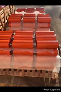
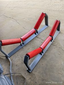
The frame is not a single part. It is a system of stringers, cross beams, legs, brackets, and mounting plates that together support the belt path. The conveyor bracket and the cross member are the interface between the frame and the idler roller, so their hole spacing and angle matter as much as the steel itself.
How the Frame Is Built
Most frames are fabricated from angle steel, channel steel, or folded steel plate. The stringers run the full length of the conveyor on both sides, and cross beams are bolted or welded between them at intervals set by the idler spacing. Legs or trestles raise the frame to the required height, and bracing keeps it square under load.
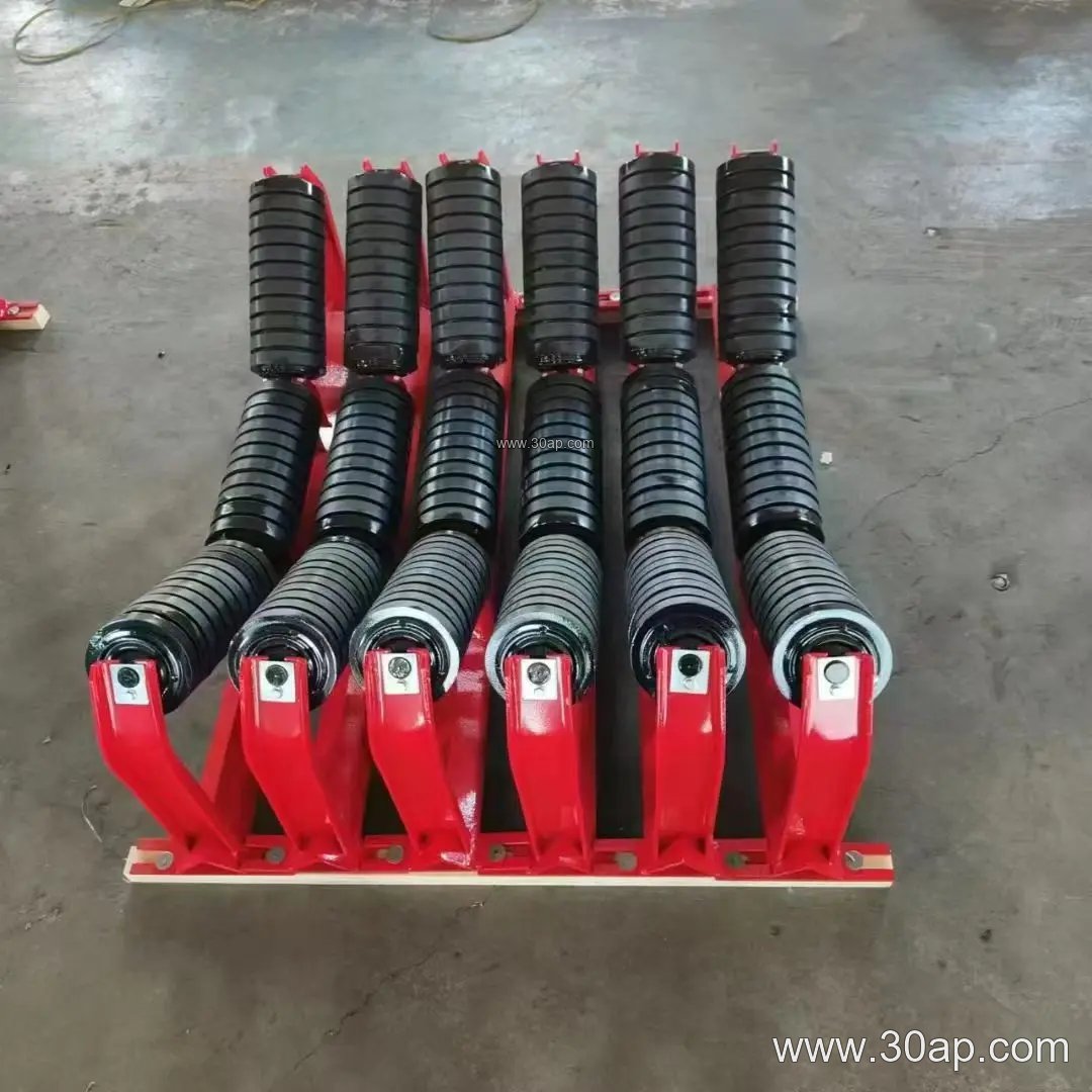
Three areas deserve attention during fabrication and assembly:
- Carrying side: the frame here usually holds troughing idler brackets that set the belt into a trough shape. Common trough angles are 20, 30, 35, and 45 degrees, and adjustable brackets can move between these angles.
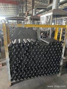
- Return side: the return frame supports flat or V-shaped return idlers that keep the belt from sagging.
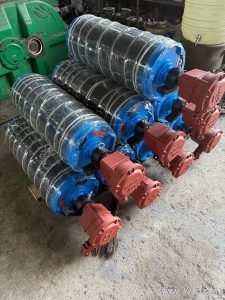
- Pulley stations: the drive pulley, tail pulley, and bend pulley each need a rigid frame section with correctly positioned bearing mounts. These pulley types are not interchangeable, and each station is designed for its own function.
Alignment is critical. A frame that is twisted or out of line will cause the belt to run off center, overload one edge of the idlers, and shorten belt life. Checking diagonals and level during installation is part of good practice.
Where Conveyor Frames Are Used
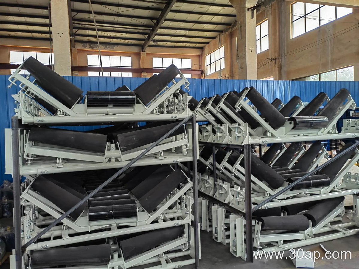
Frames appear wherever bulk material moves on a belt. In a sand and gravel line, they carry the belt through crushing and screening stages. In a coal preparation plant or a power station coal yard, they support long runs between transfer towers. In a cement plant, they handle clinker and raw material. They also serve in fertilizer plants, grain silos, and tunnel spoil removal.
The environment shapes the design. Dust, moisture, and heavy impact at loading points may call for buffer idler brackets or reinforced frame sections. Long overland runs need frames that stay aligned through temperature changes and ground settlement.
Frame Types and Typical Reference Data
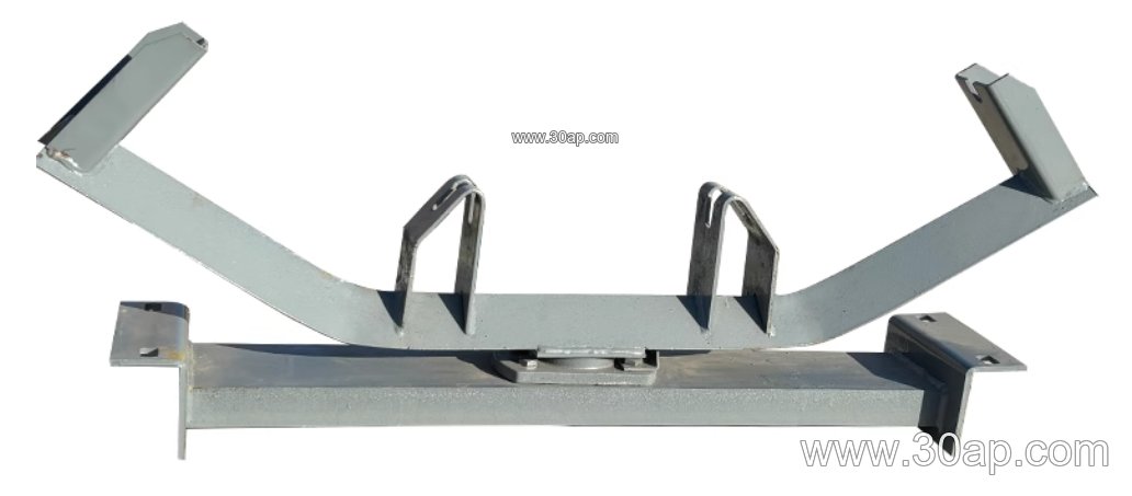
Frame configurations are usually named after the idler arrangement they carry. Common types include troughing bracket frames, transition frames, return frames, V-return frames, buffer frames, self-aligning frames, and adjustable frames. The table below gives reference ranges; actual dimensions are set by the conveyor design.
| Parameter | Common reference values |
|---|---|
| Belt width | B500, B650, B800, B1000, B1200, B1400, B1600, B1800, B2000, B2200 |
| Trough angle | 20°, 30°, 35°, 45° (adjustable brackets cover a range) |
| Idler diameter | Ø89, Ø108, Ø133, Ø159, Ø194 |
| Material | Angle steel, channel steel, folded steel plate |
| Forward tilt | Typically about 1.5° to 2° for forward-tilted brackets |
These values are reference data, not fixed combinations. A B800 conveyor might use 35 degrees with Ø108 idlers, or B1200 with 45 degrees and Ø133, but the final match depends on belt speed, load, and material. Hole spacing and cross beam length vary with belt width and trough angle, so they should be confirmed from the drawing.
What Buyers Should Check
When specifying a conveyor frame, start with the belt width and the required trough angle, then confirm the idler diameter so the bracket holes match. Ask for the frame drawing, including cross beam spacing and leg heights. Check whether the frame is bolted for site assembly or welded in sections, since this affects transport and installation.
Consider the pulley stations separately. The drive pulley, tail pulley, and bend pulley need their own bearing supports and take-up arrangements, and the frame must leave room for maintenance. For dusty or wet sites, discuss surface treatment and drainage. Finally, confirm that the frame can be adjusted for alignment after installation, because a rigid but misaligned frame is harder to correct than an adjustable one.