What Conveyor Bracket Fabrication Covers
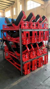
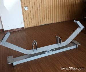
Conveyor bracket fabrication is the metalwork behind every stable idler station on a belt conveyor. In practice, the term covers the cutting, bending, drilling and welding of the steel frames that hold idler rollers in position along the carrying and return sides of the belt. A finished bracket set, often called a conveyor bracket or idler frame, keeps the conveyor belt at the intended profile, resists the load of material, and allows rollers to be replaced without disturbing the rest of the structure.
Fabrication quality matters most where dust, moisture and continuous load are present, such as a limestone quarry, a coal washing plant or a power station coal handling line. A bracket that is square, correctly drilled and properly reinforced will hold alignment far longer than a light frame that distorts during welding.
How a Bracket Set Is Built
Most frames start from angle steel, channel steel or folded steel plate. The fabricator cuts the sections to length, punches or drills the mounting holes, then jigs the parts before welding so that the trough angle and roller spacing stay true. Distortion control is a practical concern: heat input should be balanced, and long crossmembers are usually checked for straightness after cooling.
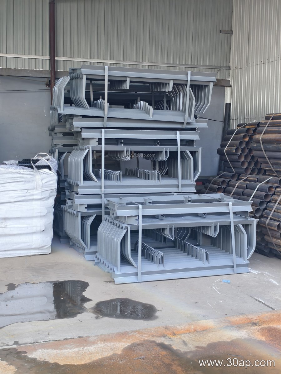
- Cutting and forming – channel or angle cut to the crossbeam length required by the belt width and trough angle.
- Drilling – roller mounting holes positioned so the idler roller sits at the correct height and angle.
- Welding and jigging – side arms fixed at the specified trough angle, with gussets added where load is highest.
- Surface treatment – shot blasting followed by painting or galvanizing, depending on the site environment.
Installation hole spacing and crossbeam length are not fixed numbers; they follow the belt width, the trough angle and the roller diameter agreed for the project.
Common Bracket Types and Where They Sit
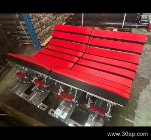
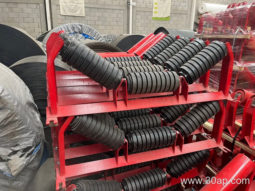
The carrying side usually uses a troughing bracket, with two or three rollers set at 20, 30, 35 or 45 degrees. A transition bracket is placed near the head and tail to ease the belt from flat to troughed. On the return side, a flat return bracket or a V-shaped return bracket supports the empty belt. Impact brackets with cushioning are fitted under loading points, while self-aligning brackets help correct belt drift on long runs.
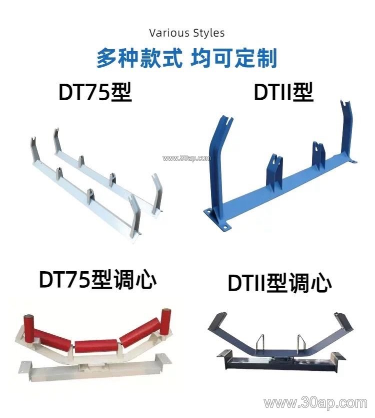
Adjustable brackets allow the trough angle to be changed within a range, which is useful during commissioning. Fixed brackets are simpler and stiffer, and suit lines where the profile is already settled. The choice between them is a design decision, not a ranking of quality.
Typical Reference Data
The values below are common reference points used when specifying fabricated frames. They are not universal rules, and the final combination is confirmed against the conveyor design.
| Parameter | Common reference values |
|---|---|
| Belt width | B500, B650, B800, B1000, B1200, B1400, B1600, B1800, B2000, B2200 |
| Trough angle | 20°, 30°, 35°, 45°; adjustable frames can move between these |
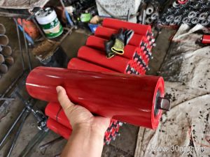
| Roller diameter | Ø89, Ø108, Ø133, Ø159, Ø194 |
| Forward tilt (leading idlers) | about 1.5° to 2° |
| Main materials | angle steel, channel steel, folded steel plate |
A frame might be described as B800, 35°, Ø108, or B1200, 45°, Ø133, or B650, 30°, Ø89. Each of these is a project-specific combination; one belt width does not lock the design to a single trough angle or a single roller diameter.
Where These Frames Are Used
Fabricated brackets appear wherever a conveyor belt runs on idlers. In a sand and gravel line they carry the loaded belt through screening and crushing stages. In a cement plant they support clinker and raw material conveyors, often in dusty conditions that demand good paint coverage. In a steel works or sintering plant they handle hot or abrasive loads, where heavier sections and impact frames are common. Port terminals and grain silos use similar frames on long transfer conveyors.
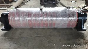
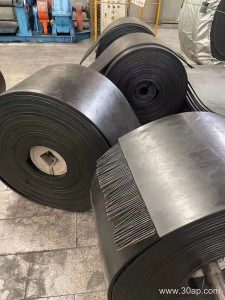
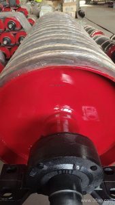
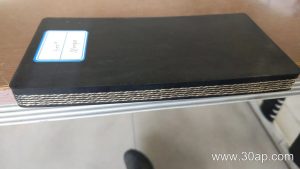
On any of these sites the bracket works together with the conveyor pulley at the drive and tail ends, the idler rollers along the run, and the belt itself. Misalignment at the pulley is often traced back to a frame that was not square, so fabrication tolerances affect the whole line.
What Buyers Should Confirm
- Belt width, trough angle and roller diameter, stated as one agreed combination.
- Mounting hole spacing and crossbeam length, taken from the conveyor layout rather than assumed.
- Material thickness and section type suitable for the load and the environment.
- Whether fixed or adjustable frames are wanted, and how adjustment is locked after setting.
- Surface treatment appropriate to the site, from standard paint to hot-dip galvanizing.
- Inspection of squareness, hole position and weld quality before dispatch.
Clear drawings and a confirmed specification list prevent most site problems. When the bracket fabrication matches the roller and belt data, installation is faster and the conveyor runs with less tracking correction later.