What a Belt Tracking Idler Does on a Conveyor
A belt tracking idler is a specially arranged roller assembly that keeps a conveyor belt centred as it travels. In a quarry, a coal handling system, or a cement plant, the belt can drift sideways because of uneven loading, misaligned structure, or a skewed roller. A tracking idler, also called a self-aligning idler or training idler, corrects that drift by steering the belt back toward the centre line. It is not the same as a drive pulley or a tail pulley; those parts transmit power or change direction, while a tracking idler works along the carrying or return run to guide the belt.
How the Assembly Is Built
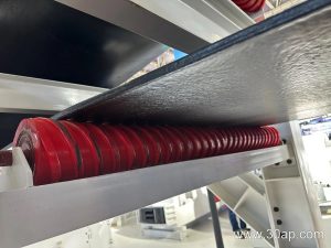
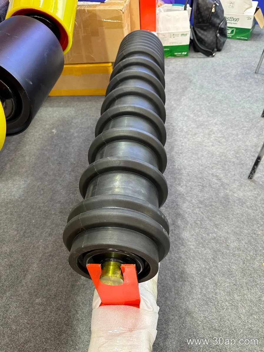
A typical unit uses two or three rollers mounted on a pivoting frame. The frame turns slightly when the belt touches a vertical guide roller or when the roller axis is offset. This small movement creates a steering force. Common idler roller diameters include Ø89, Ø108, Ø127, and Ø159, though the right size depends on belt width and load. Roller shells are often steel tube, nylon, or rubber-covered. Bearings such as 6204, 6205, 6305, 6306, or 6308 are selected by the manufacturer according to speed and duty. The idler is supported by a conveyor bracket that allows rotation or angular adjustment.
Common Types and Arrangements
- Friction self-aligning idler – uses friction between the belt and a side roller to pivot the frame.
- Tapered self-aligning idler – uses tapered rollers to create a centring effect.
- Return V-type idler – used on the return strand to guide the belt from below.
- Three-roll troughing set – the carrying side version, often with 20°, 30°, 35°, or 45° trough angles.
These types are not interchangeable with a bend pulley or a drive pulley. A bend pulley changes belt direction at a transfer point, while a tracking idler only corrects lateral position.
Where It Fits in a Conveyor System
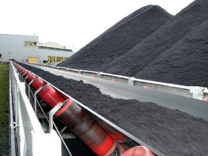
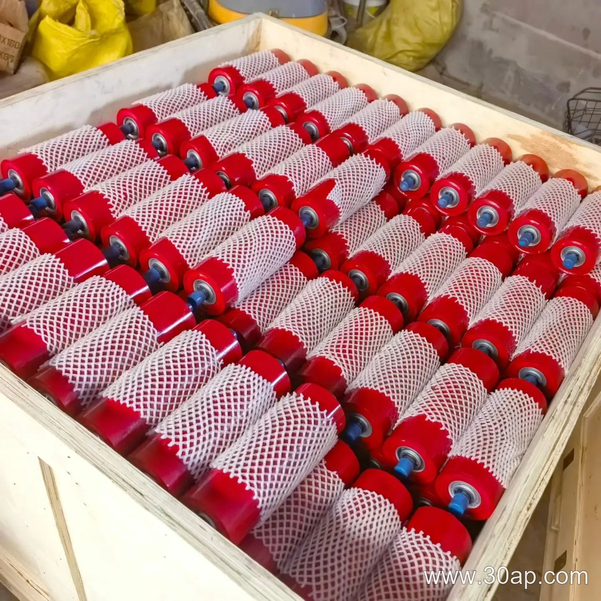
Tracking idlers are placed at intervals along the carrying run and the return run. In a limestone mine or a power plant coal yard, they are often installed before the head pulley, after the loading point, and on long straight sections. A belt tracking idler works together with the conveyor belt, the idler roller, and the conveyor bracket to keep material from spilling. It is especially useful where the belt is long, where loading is off-centre, or where wind and rain affect an outdoor installation.
Typical Reference Data
The following values are common examples, not fixed rules. Always confirm with the conveyor design.
| Belt width | Common roller length for three-roll troughing (mm) | Common trough angle |
|---|---|---|
| B500 | 200 | 20°–35° |
| B650 | 250 | 20°–35° |
| B800 | 315 | 20°–45° |
| B1000 | 380 | 20°–45° |
| B1200 | 465 | 20°–45° |
| B1400 | 530 | 20°–45° |
| B1600 | 600 | 20°–45° |
Roller diameter and bearing size are selected separately. A B800 belt does not automatically require a Ø108 roller, and a Ø127 roller can be used on several belt widths. The shaft diameter is also a design choice, not a direct result of belt width alone.
What a Buyer Should Check
- Belt width and trough angle – these affect roller length and frame geometry.
- Roller diameter and bearing – match to load, speed, and environment.
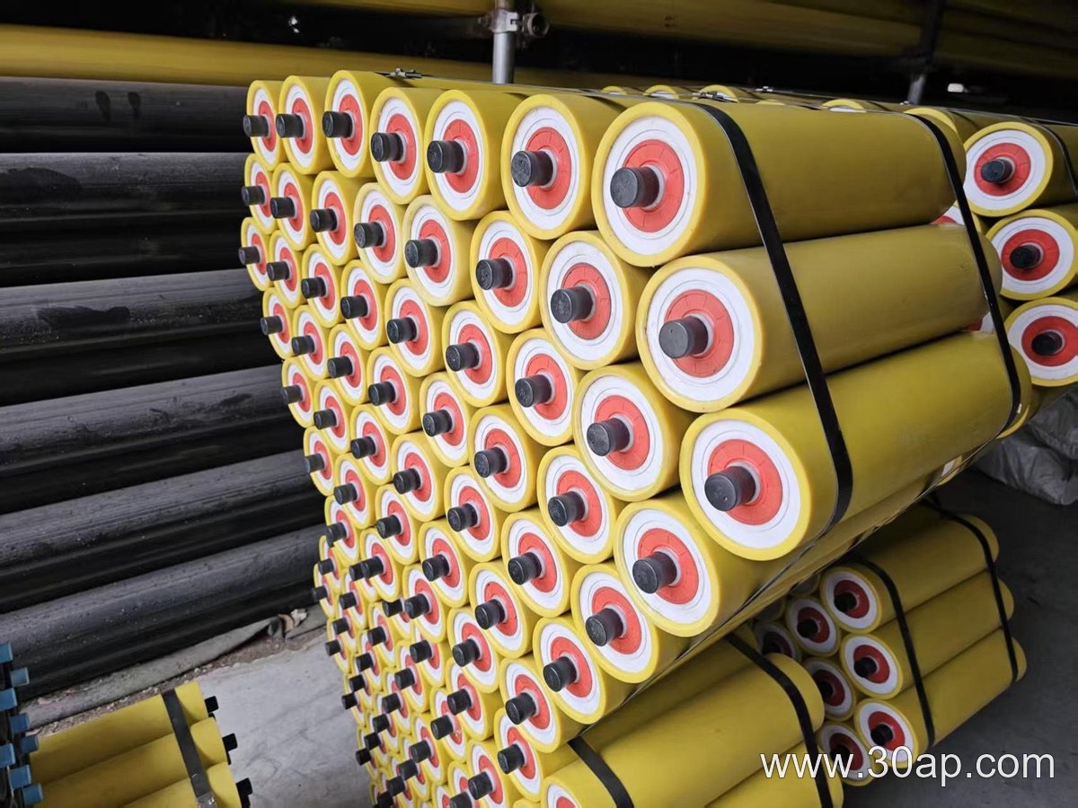
- Roller surface – steel, nylon, ceramic, or rubber rings for different wear conditions.
- Mounting bracket – must fit the existing conveyor bracket spacing.
- Maintenance access – a tracking idler should be easy to inspect and adjust.
In a sand and gravel line or a fertilizer plant, dust and moisture can shorten bearing life. Sealed bearings and proper greasing help. A belt tracking idler is not a substitute for correct pulley alignment or belt splicing, but it is a practical way to reduce edge damage and spillage. For best results, combine tracking idlers with regular inspection of the conveyor belt, idler rollers, and conveyor pulleys.