How to Keep a Conveyor Bracket Stable on a Wet Outdoor Conveyor in a Stormwater Treatment Plant
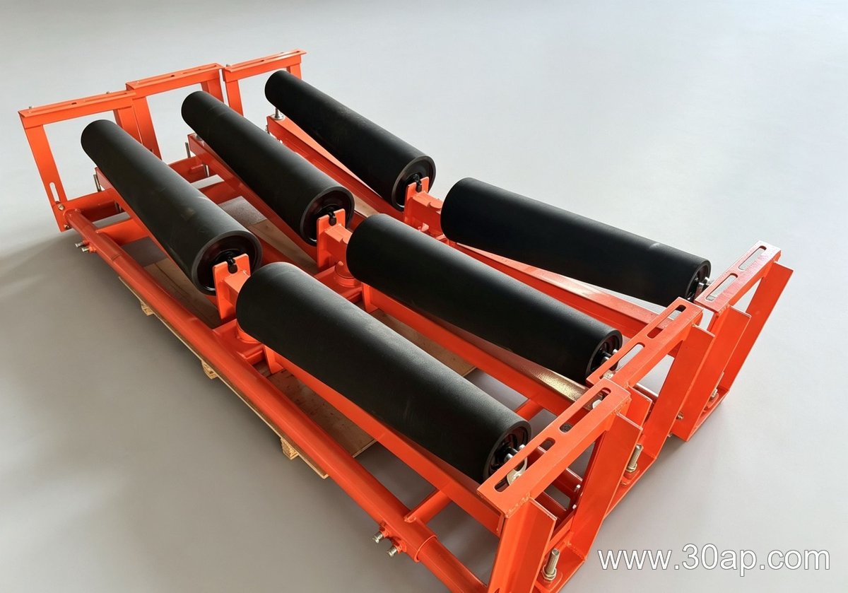
In a stormwater treatment plant, a conveyor bracket that supports idler rolls on an outdoor belt must survive constant moisture, intermittent flooding, and temperature swings. The design trade-off is between drainage and stiffness: an open bracket shape sheds water but may flex under load, while a closed box section is rigid but traps water and accelerates corrosion. The right conveyor bracket balances these needs by combining a self-draining profile with enough section depth to resist bending.
Why a Wet Outdoor Conveyor Demands a Different Bracket Approach
Unlike a dry indoor line, a wet outdoor conveyor exposes the bracket to rain, wash-down, and grit-laden splash. Water sitting on flat surfaces or inside pockets promotes rust at bolt holes and weld toes. A conveyor bracket for this setting should be mounted so that water runs off, not into, the structure. In a stormwater treatment plant, the bracket often sits below the belt line, making it a natural collection point for debris and moisture.
Material and finish choices that suit wet service
- Hot-dip galvanized steel offers a thick zinc coating that protects cut edges and threads; it is a common choice for outdoor conveyor brackets.
- Stainless steel resists chlorides and acids but costs more and may require different fasteners to avoid galvanic corrosion.
- Powder coating over mild steel can chip at impact points, so it is less reliable where grit or stones strike the bracket.
Design details that prevent water traps and looseness
A conveyor bracket with a sloped top face or a drain hole at the lowest point reduces standing water. Rounding or chamfering edges helps coatings adhere and removes thin spots that rust first. For bolted connections, use serrated flange nuts or thread-locking compound, because vibration and thermal cycling on an outdoor conveyor can loosen standard nuts over time. If the bracket is welded to the frame, specify a continuous fillet rather than stitch welds to keep moisture out of the joint.
Inspection and maintenance in a stormwater treatment plant
After heavy rain, check the conveyor bracket for pooled water, loose bolts, and white rust on galvanized surfaces. A quick rinse with clean water and a brush removes silt that holds moisture. Replace any bracket showing deep pitting or cracked welds, because a failed bracket can misalign the idler roll and damage the belt. These steps are simple but they extend the service interval of the whole conveyor line.
FAQ: Wet-Environment Conveyor Bracket Concerns
Can a standard conveyor bracket be used outdoors?
Only if its material and finish suit wet conditions. Standard painted brackets often fail early in rain or wash-down areas; specify galvanized or stainless steel for outdoor duty.
How do I stop water from collecting on the bracket?
Choose a self-draining shape, add drain holes at low points, and mount the bracket so surfaces slope toward the drain. Avoid upward-facing channels that trap water.
What fasteners work best in a wet conveyor bracket?
Use fasteners with the same or nobler corrosion resistance as the bracket, and add locking features to resist vibration. For example, galvanized bolts with galvanized brackets, or stainless bolts with stainless brackets, when the assembly is not exposed to chlorides.
Conveyor Belt Specification for a Constrained Port Terminal
This engineering example is entirely hypothetical. It assumes a bulk-material port terminal handling coal or iron ore, where a new conveyor belt must fit into an existing gallery with limited headroom and frequent dust exposure. The goal is to explain a design sequence, not to present a real installation.
Assumptions and Constraints
- Design capacity: 2,500 t/h (hypothetical).
- Belt width: 1,200 mm to match existing chute geometry.
- Center-to-center length: 180 m with a 12° incline.
- Ambient conditions: 0–40°C, high humidity, coal dust.
- Space limit: minimum pulley diameter and take-up travel are fixed.
Step 1: Determine the Required Belt Strength
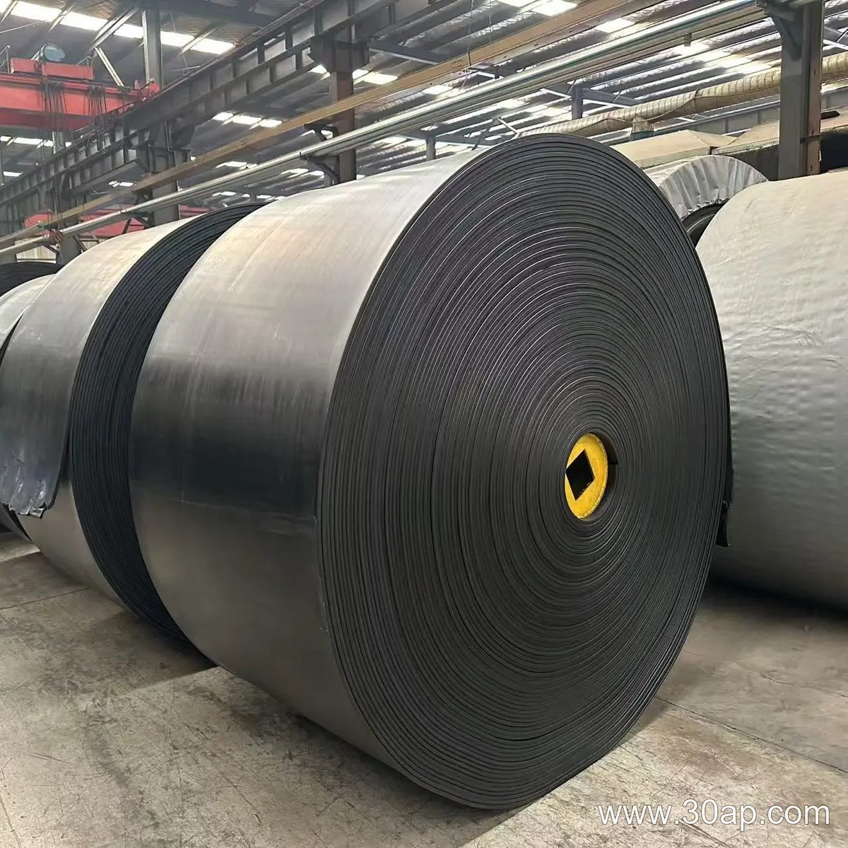
Using the hypothetical capacity and incline, calculate the effective tension. For a rough estimate, use the simple formula P = (C × L × v × (m + mb) × g) / 1000, where C is a friction factor, L is length, v is belt speed, m is material mass per meter, and mb is belt mass per meter. Assume a friction factor of 0.02 for a dusty environment. This gives a starting point for belt tension and, therefore, the required cord strength. A belt such as an ST3150 conveyor belt, which uses steel cords, would be one option if the calculated tension exceeds fabric belt limits. However, the final choice must come from a detailed calculation and supplier data.
Step 2: Choose Cover Grade for Dust and Impact
Coal dust is abrasive but not highly cut-resistant. A cover grade with good abrasion resistance and moderate cut resistance is usually more cost-effective than the hardest available compound. The cover thickness should account for wear from the loading point and skirtboard. If the terminal also handles occasional chemical exposure, a chemical resistant conveyor belt cover may be justified, but that is a separate decision based on actual material analysis.
Step 3: Check Belt Width and Speed
A 1,200 mm belt running at 3.5 m/s can carry the assumed capacity with a standard trough angle. If the existing structure cannot accept that speed, a wider belt may be needed, but that increases weight and pulley loads. Since the gallery height is fixed, a wider belt might not fit. Therefore, the design team would likely keep the 1,200 mm width and adjust the load profile or speed within the drive limits.
Step 4: Address Dust and Spillage
Dust control is not solely a belt property. The belt should have a smooth cover to reduce material carryback, and the skirt rubber should be adjusted to minimize gaps. A belt with a slightly rougher cover might improve grip on inclines but can trap dust. For this hypothetical terminal, a smooth cover with good abrasion resistance is the better trade-off.
Step 5: Verify with a Full Engineering Study
This example only outlines the decisions. A real project requires a full conveyor design, including acceleration, take-up, and safety factors. The main takeaway is that the conveyor belt cannot be selected in isolation; it must match the terminal’s geometry, material, and maintenance strategy.
Setting the Hypothetical Project
Suppose a quarry needs a new conveyor to carry 250 t/h of crushed granite along a 60 m incline. The belt is 800 mm wide and runs at 1.5 m/s. The environment is dusty, with fines settling on every surface. For this project, we must select an idler roller that supports the belt without premature seizure or excessive wear. All values here are assumed for illustration, not taken from a real installation.
Step 1: Estimate the Load on the Idler Roller
The first decision is the load rating. Using a simplified approach, we estimate the material load per meter: 250 t/h ÷ (3.6 × 1.5 m/s) ≈ 46.3 kg/m. Add the belt weight, assume 15 kg/m. Total ≈ 61.3 kg/m. With a 1.2 m idler spacing on the carrying side, each idler roller supports about 73.6 kg of belt and material. For the return side, the load is only the belt, so about 18 kg per idler. These are rough figures, but they set the minimum static load. In a dusty quarry, we also add a dynamic factor for impact at the loading point and for misalignment. A conservative choice would be an idler roller rated for at least 150 kg working load, even though the calculated static load is lower.
Step 2: Choose the Roller Diameter and Bearing Type
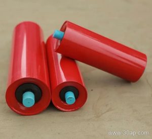
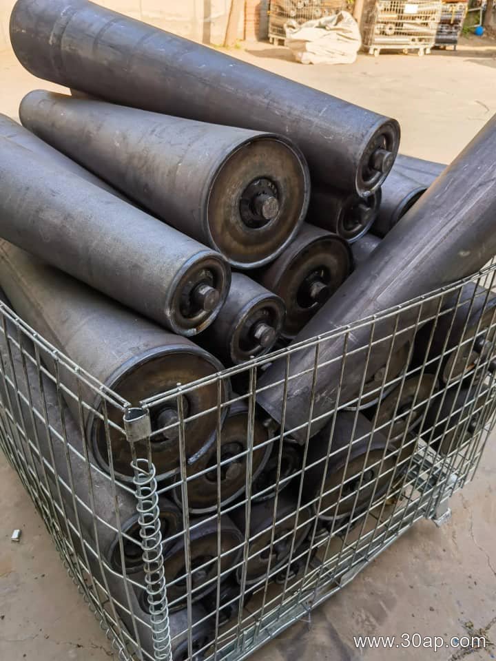
Belt speed and lump size influence diameter. For 1.5 m/s and granite lumps up to 150 mm, a 127 mm diameter idler roller is a reasonable starting point. Larger diameters reduce rotational speed and improve bearing life in dust. However, the existing structure limits the gap between the belt and the frame. Assume a maximum clearance of 200 mm from the belt line to the top of the support. A 127 mm roller with a 30 mm shaft and a standard housing fits comfortably. If clearance were tighter, a smaller diameter or a different bearing seal would be needed. For dust, we specify a contact seal with a grease-filled labyrinth. This is not a universal specification, but it is a common approach to keep fines out.
Step 3: Material and Construction Decisions
The shell material matters. In a quarry, abrasive dust can wear through thin-wall tubes quickly. We choose a 4 mm wall thickness steel shell with a protective coating. Polymer rollers are lighter and resist buildup, but they may not handle the same impact load. For this hypothetical project, steel is the safer default. The shaft is 30 mm diameter, turned and chamfered to avoid stress concentrations. The end caps are welded, not pressed, to reduce the risk of loosening under vibration. These decisions are based on the assumption of continuous operation, 16 hours per day, five days per week.
Step 4: Check the Arrangement and Spacing
Using a 35° trough angle, three idler rollers per set support the belt. The center roller carries less load than the side rollers in a trough, but the side rollers see more abrasion from the material edge. For the return strand, a single flat idler roller is sufficient. We space carrying idlers at 1.2 m and return idlers at 3 m. This spacing is a starting point; if belt sag exceeds 2% of the span, we would reduce spacing. The quarry dust means we also avoid any open bearings or unprotected grease nipples.
Summary of Assumptions and Outcome
- Hypothetical conveyor: 250 t/h, 800 mm belt, 1.5 m/s, 60 m incline.
- Calculated static load per carrying idler roller: ~74 kg; selected rating: 150 kg for dust and impact.
- Roller diameter: 127 mm; shaft: 30 mm; seal: labyrinth with grease.
- Shell: 4 mm steel; end caps welded; spacing: 1.2 m carrying, 3 m return.
This exercise shows that idler roller selection is not just about matching a catalog number. It requires estimating load, checking clearance, and choosing construction details that suit the dust and duty. The numbers here are illustrative; a real project would need verified belt tensions, material properties, and structural limits.
What exactly is a conveyor pulley?
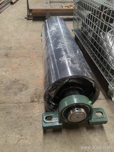
A conveyor pulley is a rotating cylindrical assembly that transmits power to the belt or changes its direction at the ends of a conveyor. In a mineral-processing plant, it must handle abrasive dust, heavy loads, and continuous operation. Unlike an idler, which only supports the belt, a conveyor pulley is a structural component with a shaft, bearings, and a shell designed for torque and tension. For example, a drive pulley in a hypothetical copper-ore plant might have a 1200 mm diameter and a 1500 mm face width to match the belt.
How does a conveyor pulley differ from a conveyor idler?
An idler is a free-turning roller that supports the belt along its carrying or return run. A conveyor pulley, by contrast, is mounted at the head, tail, or bend points and often drives or redirects the belt. Idlers typically use small-diameter tubes and low-friction bearings, while a conveyor pulley has a robust shell, a larger shaft, and sometimes lagging for grip. In a mineral-processing plant, confusing the two can lead to misdiagnosis: belt mistracking might be blamed on idlers when a worn tail pulley is the real cause.
What are common types of conveyor pulleys?
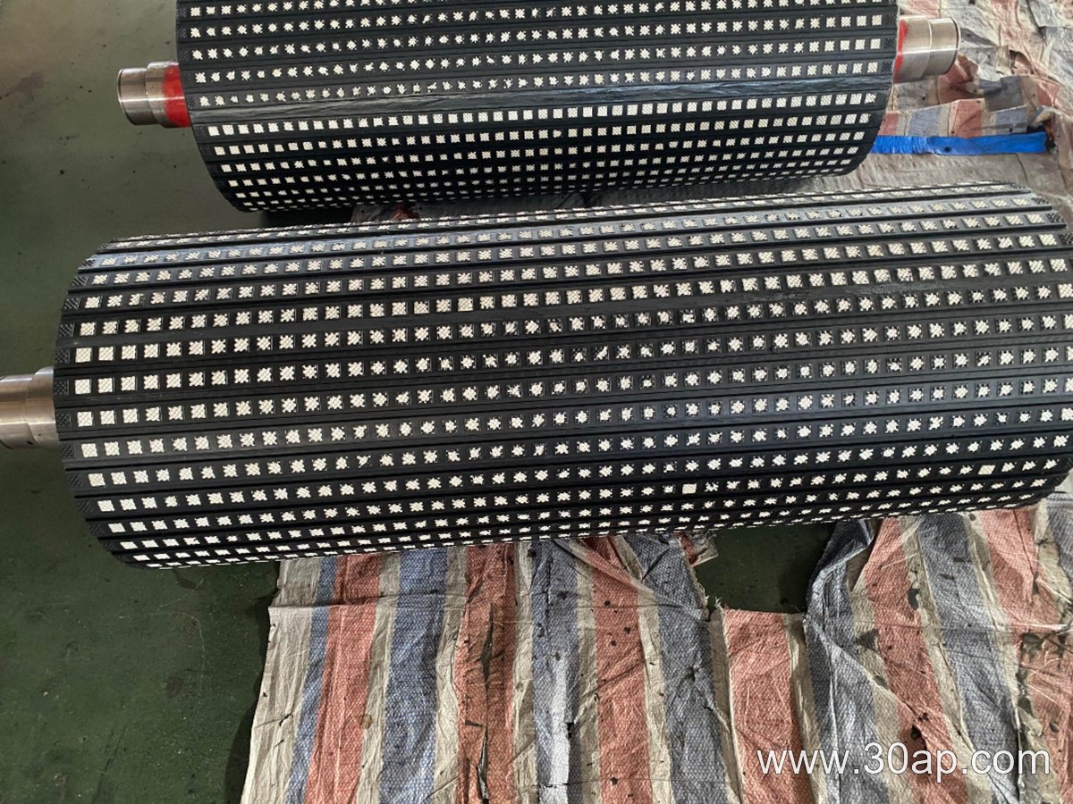
Drive pulleys transmit motor torque to the belt. Tail pulleys redirect the belt at the load end. Bend pulleys change direction in multi-pulley systems. Take-up pulleys maintain tension. Each type may be specified with different features. For instance, a hypothetical tail pulley in a wet mineral-processing plant might use a welded design with a rubber lagging to improve traction and shed water. A drive pulley in the same plant might have a larger shaft to handle higher torque.
When is a conveyor pulley preferred over a roller?
Use a conveyor pulley when you need to transfer significant power, change belt direction under tension, or handle heavy loads. Rollers are fine for light-duty support. In a mineral-processing plant, the head pulley is always a conveyor pulley because it drives the belt. A bend pulley is also a conveyor pulley because it must withstand tension. If you replace a conveyor pulley with a roller, the shaft may fail or the belt may slip.
How do you inspect a conveyor pulley in service?
Check for lagging wear, shell cracks, shaft deflection, and bearing temperature. Listen for unusual noise. In a mineral-processing plant, abrasive dust can penetrate seals; look for grease leaks. A hypothetical weekly check might include measuring lagging thickness at several points. If the lagging is worn below half its original thickness, plan replacement. Also verify that the pulley is square to the belt centerline; misalignment causes edge wear.