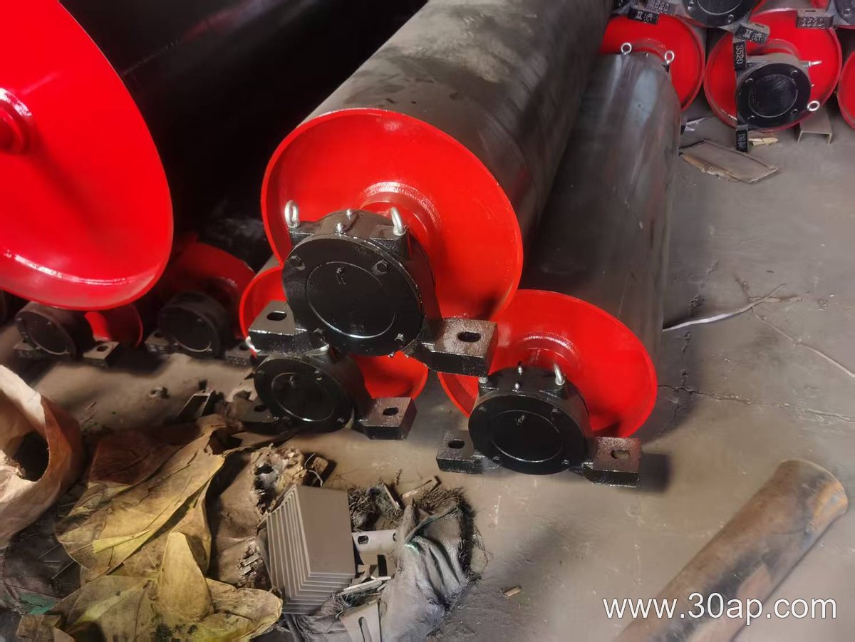
How Do You Keep a Conveyor Pulley Reliable When It Operates Outdoors in Constant Wetness?
Start with a direct answer: a conveyor pulley in a wet outdoor environment needs a scheduled inspection routine that focuses on water ingress, corrosion, lagging condition and belt tracking. Preventive maintenance should center on sealing, drainage and surface protection. Replacement becomes necessary when corrosion, slippage or structural damage pass defined limits.
Inspection Points for a Wet Outdoor Conveyor Pulley
Begin each inspection with the pulley itself, not the belt or idlers. Check the following:
- Lagging wear and water retention: look for grooves, glazing or trapped moisture between the lagging and shell.
- Shaft seals and bearing housings: confirm that water is not entering through worn lip seals or loose covers.
- Drainage paths: ensure that water can escape from the pulley area instead of pooling around the drum.
- Shell and end-disc corrosion: inspect for pitting, scale or rust streaks that indicate coating breakdown.
- Belt tracking: watch for the belt wandering to one side, which may mean a misaligned or deformed pulley.
Preventive Maintenance Actions for a Conveyor Pulley
Preventive maintenance in wet conditions is mostly about keeping water away from critical surfaces. Re-torque fasteners on lagging and bearing caps at recommended intervals. Clean drain holes and remove debris that can block water flow. Apply compatible corrosion-resistant coatings to exposed shell areas. Check that the pulley rotates freely by hand during shutdowns; a stiff bearing may signal water contamination. If the conveyor runs intermittently, rotate the pulley periodically to prevent localized corrosion at the belt contact area.
Signs That a Conveyor Pulley Needs Replacement
Some wear is normal, but certain conditions justify replacement rather than continued repair. Replace the conveyor pulley when:
- Lagging is worn through to the shell or has large missing sections that reduce grip.
- Corrosion has caused deep pitting or visible cracks in the shell or end discs.
- Bearing housings are badly worn or the shaft is bent, causing persistent vibration.
- Water ingress has ruined the bearing lubrication and the pulley cannot be re-sealed reliably.
- Belt slippage continues after lagging and tension adjustments, indicating a permanent loss of friction.
For a wet outdoor conveyor, a replacement conveyor pulley with sealed-for-life bearings, improved drainage and a corrosion-resistant lagging may reduce future maintenance. Always verify dimensions and load capacity before ordering.
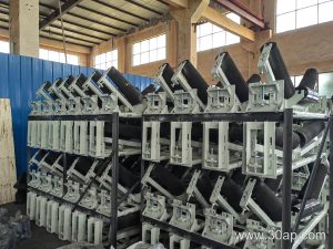
Reading a Conveyor Bracket Specification Sheet: Fields, Units, and What They Mean
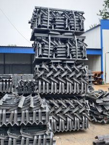
A common misconception is that a conveyor bracket specification is just a part number and a material grade. In reality, a proper specification sheet contains several fields that tell you how the bracket fits, how strong it is, and how it should be installed. In a cement plant, where dust and vibration are constant, reading these fields correctly can prevent misalignment and premature wear. This article explains the main specification fields, their units, and how to interpret them without assuming any universal ratings.
Key Specification Fields for a Conveyor Bracket
Specification sheets vary by manufacturer, but most include the following fields. Each field has a unit or a defined meaning that you must match to your application.
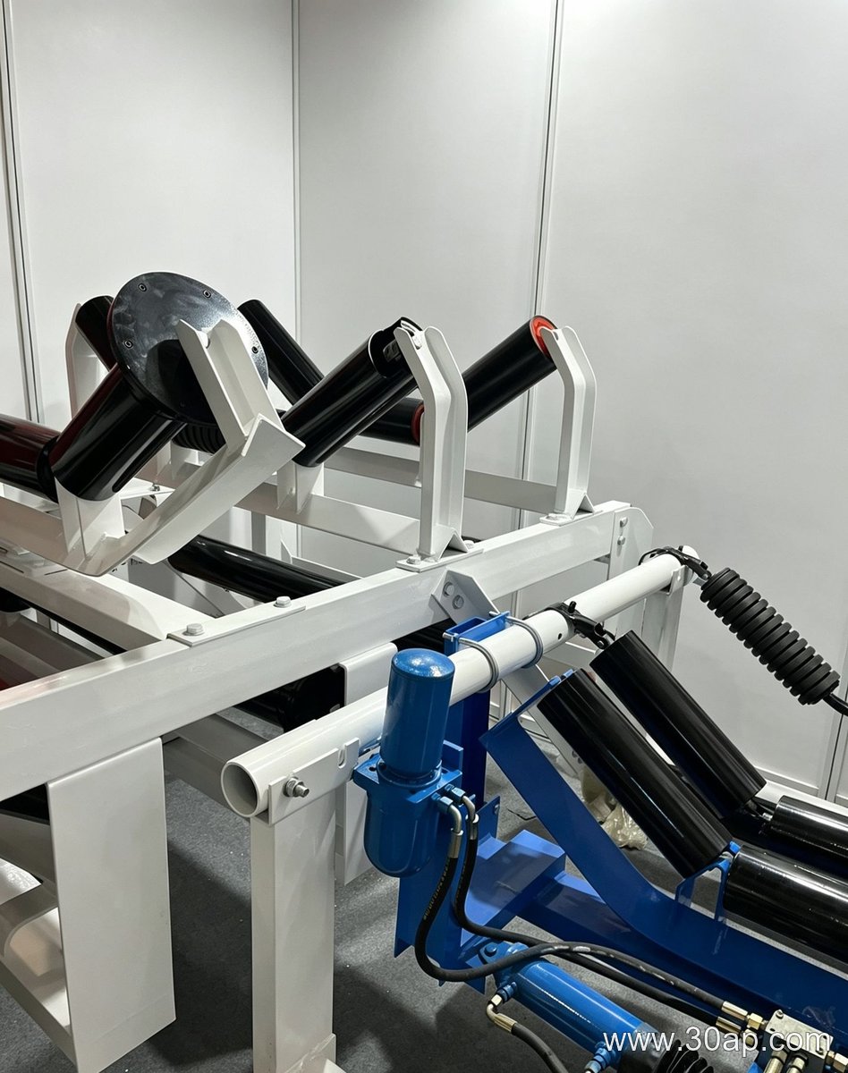
- Mounting hole diameter: Usually in millimeters (mm). This tells you the bolt size the bracket accepts. For example, a 12 mm hole fits an M12 bolt. Do not confuse hole diameter with bolt diameter—clearance matters.
- Bolt hole spacing: Center-to-center distance, also in mm. This must match the frame or structure where the bracket attaches. A mismatch means the bracket will not bolt down without drilling new holes.
- Load capacity: Often stated in kilonewtons (kN) or kilograms (kg). This is the maximum static load the bracket is designed to support, but it depends on the load direction and safety factor. Never treat it as a universal limit for dynamic or impact loads.
- Material grade: For carbon steel, you might see designations like Q235 or S355. These are yield strength indicators, not guarantees of corrosion resistance. In a cement plant, consider whether the bracket will be painted, galvanized, or left bare.
- Angle or offset: Some brackets are angled to match idler troughing. This field, in degrees (°), affects belt contact and tracking. A 20° bracket is not interchangeable with a 35° bracket.
- Finish: Coating type (e.g., hot-dip galvanized, powder-coated) and thickness in micrometers (µm). This influences abrasion and corrosion performance.
How to Interpret Units and Avoid Assumptions
Units are not decorative. A load capacity in kN is not the same as a working load limit in kg. For example, a bracket rated at 10 kN is not automatically safe for a 1,000 kg dynamic load—you must apply the appropriate safety factor and consider fatigue. Similarly, a hole spacing in inches must be converted to millimeters if your frame is metric. Always check whether the specification gives a minimum or maximum value, and whether it applies to a single bracket or a pair. When in doubt, request a detailed drawing rather than relying on a summary table. In a cement plant, dust buildup can add unexpected weight; a bracket that meets a static rating may still need a higher margin for continuous operation. Treat every numerical value as a starting point for engineering verification, not as a final answer.
Why the Conveyor Belt Is Often Blamed First
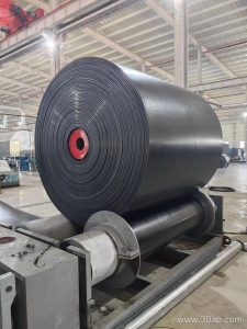
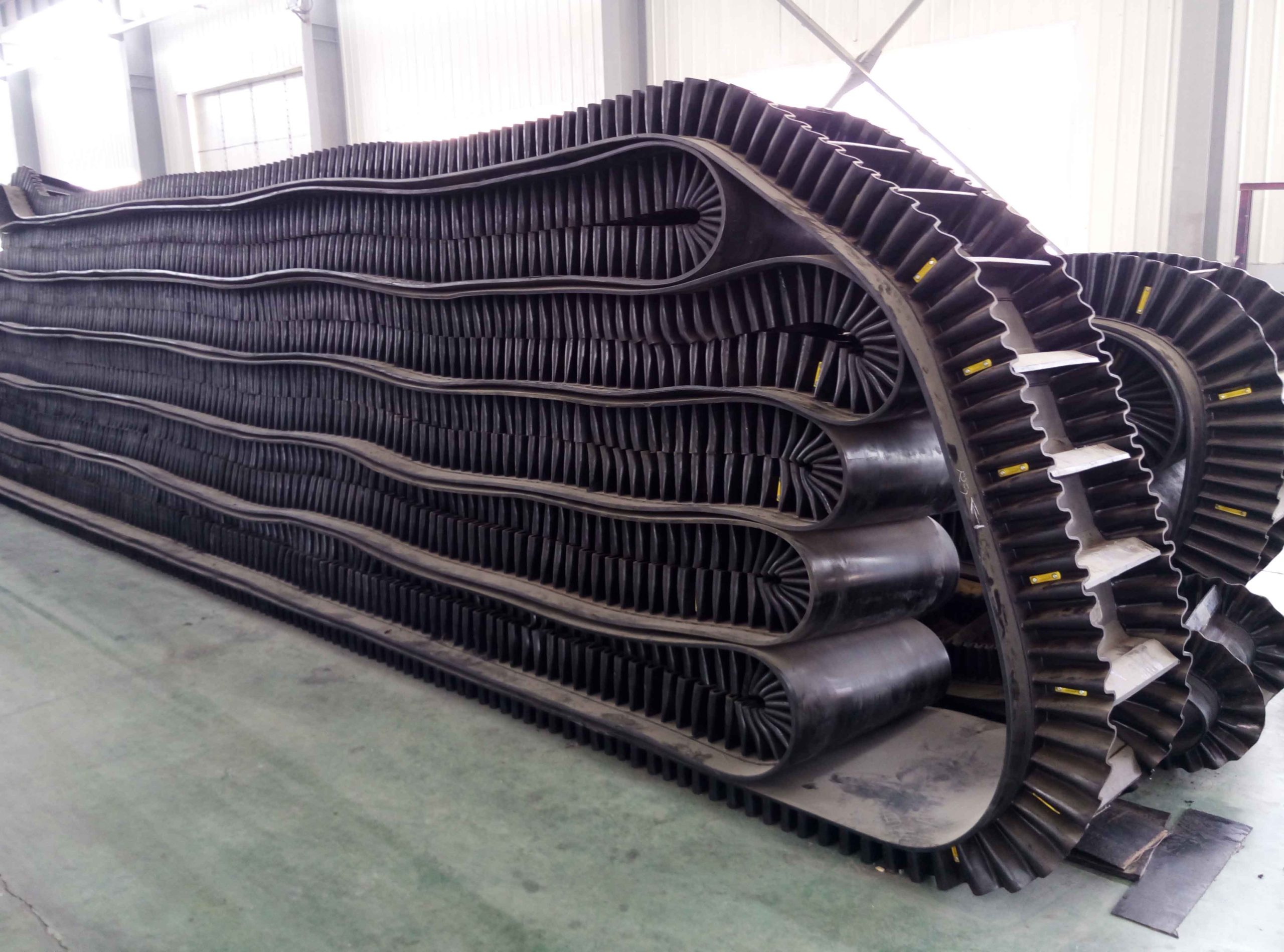
On a general manufacturing line, spillage at the transfer point is a common challenge. Operators often suspect the conveyor belt itself is worn or misaligned. In reality, the belt is frequently a symptom, not the root cause—but its selection and integration are still central to the fix.
The Mechanism: How Material Escapes
At a transfer point, material leaves one conveyor belt and lands on the next. If the receiving conveyor belt moves too fast or too slow relative to the load, or if the chute is poorly designed, fines and small parts bounce off. The belt’s surface profile, speed, and tension all affect how well it contains the material.
Integrating the Right Conveyor Belt into the Solution
A practical solution combines chute geometry, skirtboards, and a conveyor belt with the right cover and edge. For a general manufacturing line handling mixed small parts, a belt with a slightly textured cover can reduce sliding. If the material is lightweight and dusty, a belt with a smooth cover and proper cleaning devices may be better. The belt must also match the pulley diameter and take-up system to avoid tracking issues.
Hypothetical Example
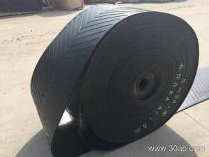
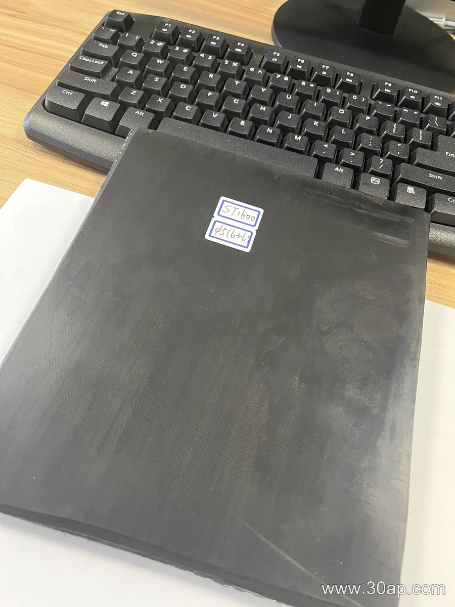
Consider a line moving 2 kg boxes and loose foam pieces at 30 m/min. A standard 2-ply belt with a 3 mm cover might work, but if spillage persists, a belt with a 1.5 mm cover and a chevron pattern could improve grip—though chevron belts require different cleaning. This is illustrative only; actual selection depends on testing.
Key Takeaways for Maintenance and Engineering
- Check belt speed and chute angle before replacing the conveyor belt.
- Ensure the conveyor belt is centered and tensioned correctly.
- Use skirt rubber that contacts the belt evenly, not too tight.
- Mark any trial belt installation as a test, and monitor spillage over time.
By treating the conveyor belt as part of a system, a general manufacturing line can reduce downtime and material loss without over-specifying the belt itself.
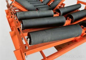
Why Material Choice Defines Idler Roller Performance in a Cement Plant
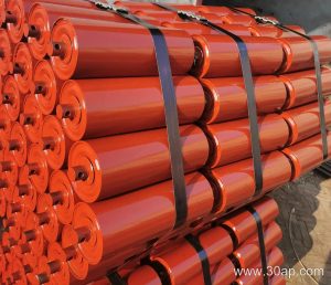
An idler roller in a cement plant has one of the least forgiving jobs on the site. Clinker dust, limestone fines, and occasional heat punish every component, so the shell and bearing housing materials matter as much as the roller’s dimensions. The wrong choice may save money at purchase and cost far more in seized bearings and belt damage.
This article compares the common material options and the trade-offs behind them. It is a selection discussion, not a report of any specific installation.
Shell Materials: Steel, Stainless, and Polymer
Carbon Steel
Carbon steel is the default shell material for general-duty idler rollers. It is strong, weldable, and readily formed into the tube profile needed for a true-running roller. Its weakness is corrosion: in wet or acidic conditions, rust pits the surface and can eventually flake into the bearing seals. Protective paint or plating helps, but abrasion at the belt contact line can wear it through.
Stainless Steel
Stainless steel resists corrosion and holds up in washdown areas or where the material being conveyed is damp. The trade-off is cost and, in some grades, lower resistance to abrasive sliding wear than hardened carbon steel. It is usually specified where corrosion, not abrasion, is the dominant failure mode.
Polymer and Composite Shells
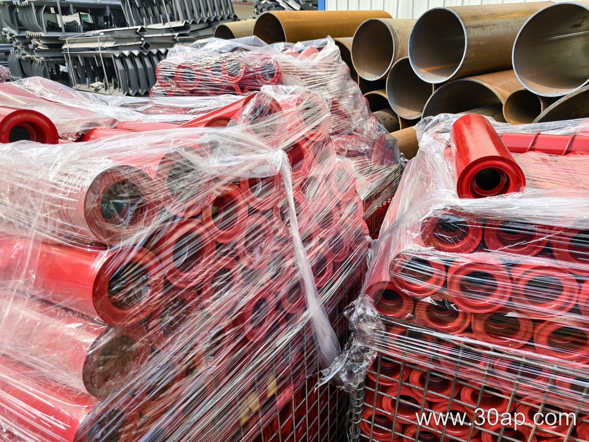
Polymer shells are light, quiet, and resistant to many chemicals, and they do not rust. In a cement plant they are most plausible on light-duty or return-side positions rather than under heavy impact at a feed point. Heat resistance and stiffness vary widely by compound, so the supplier’s temperature and load data must be checked rather than assumed.
Bearing Housings, Seals, and Shafts
The housing and seal arrangement often determines service life more than the shell does. Cast iron housings are common and rigid; stamped steel housings are lighter and cheaper. For dusty cement service, a labyrinth or multi-stage seal is generally preferred over a simple contact seal, because fine clinker dust penetrates easily and grinds a bearing to failure.
- Shaft material: usually carbon steel; stainless where corrosion is a concern
- Bearing type: sealed ball bearings for most positions; tapered or spherical bearings for heavy radial loads
- Seal choice: labyrinth or combined labyrinth-and-contact for abrasive dust
- Fasteners and end caps: plated or stainless to prevent seizing during maintenance
Balancing Cost, Wear Life, and Maintenance Access
Premium materials rarely pay back in every position. A practical approach is to match the roller to its duty: heavy steel with robust sealing at impact and load points, and lighter or polymer rollers on low-load return runs. Because replacement labor in a cement plant is often the largest cost, materials that extend service life or simplify removal can be justified even at a higher unit price.
Hypothetical example: for a dusty clinker conveyor, a steel shell with a labyrinth seal and cast housing is a reasonable starting point; a polymer roller in the same position would be difficult to justify without documented heat and load ratings from the supplier.