Why Material Selection Defines Conveyor Bracket Performance at a Port Terminal
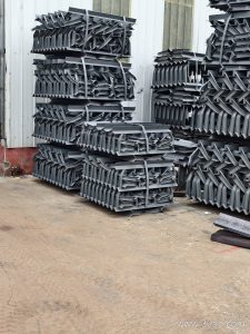
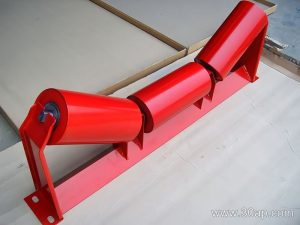
At a bulk-material port terminal, a conveyor bracket must endure salt-laden air, abrasive dust, and continuous heavy loads. The material you choose for this structural component directly affects how often it needs replacement and how well it maintains belt alignment. This article compares common material options and their trade-offs.
Carbon Steel: The Workhorse with a Corrosion Caveat
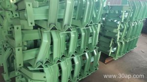
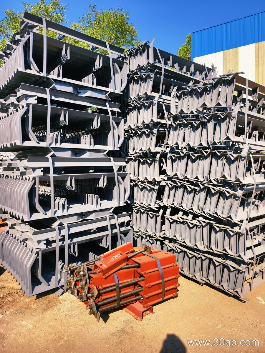
Carbon steel is a frequent choice for conveyor brackets because it offers high strength at a moderate cost. It can be formed, welded, and machined easily, making it suitable for custom idler frames and support brackets. However, in a port environment, unprotected carbon steel corrodes quickly. Hot-dip galvanizing or a robust paint system is essential. Even then, edges and welds may need extra attention. The trade-off is clear: low upfront cost and high strength, but ongoing maintenance to combat rust.
Stainless Steel: Corrosion Resistance at a Premium
When salt spray and humidity are relentless, stainless steel brackets—such as grades 304 or 316—resist corrosion far better than carbon steel. Grade 316, with its molybdenum content, performs especially well in chloride-rich coastal air. The downside is cost: stainless steel is significantly more expensive and can be more difficult to machine. It is typically reserved for critical, hard-to-replace brackets or areas with the most severe exposure.
Aluminum: Lightweight but Limited
Aluminum brackets are lightweight and naturally resistant to atmospheric corrosion. They are easier to handle during installation and reduce structural load. However, aluminum has lower yield strength than steel and may not withstand the impact forces from large lump material at a port terminal. It also has poor fatigue resistance in high-vibration applications. For light-duty or low-impact zones, aluminum can be a viable option; for primary load points, steel is usually preferred.
Trade-Offs in Coatings and Construction
Material choice is not only about alloy. The construction method—whether a bracket is welded or bolted—also matters. Welded carbon steel brackets can be galvanized, but the process may distort thin sections. Bolted designs allow mixed materials, such as stainless bolts in a carbon steel frame, but create potential galvanic corrosion sites. In a port terminal, specifying the right material and finish for each bracket location is a balancing act between initial cost, maintenance access, and expected service life.
Choosing Between Rubber-Covered Fabric and Steel-Cord Conveyor Belts for Wet Outdoor Stockyards
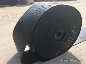
Designing a conveyor belt for a wet outdoor stockyard involves a trade-off between flexibility and tensile capacity. Rain, standing water, and temperature swings punish the carcass and covers, so the choice between a rubber-covered fabric conveyor belt and a steel-cord conveyor belt affects splicing, idler training, and long-term reliability. The comparison below is illustrative and uses hypothetical project conditions; actual selection depends on load, span, and site data.
Rubber-Covered Fabric Conveyor Belt
This subtype uses multiple plies of woven fabric embedded in rubber, with protective covers on both faces. It excels on shorter to medium center distances where flexibility and easy splicing matter.
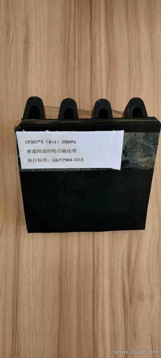
- Benefits: Tolerant of misalignment, simpler mechanical splicing, lower pulley diameters, and good resistance to impact from wet, lumpy material.
- Limitations: Lower tensile strength per unit width than steel cord, greater stretch under load, and fabric plies can wick moisture if edges are damaged.
- Suitable conditions: Outdoor yards with moderate belt widths, frequent repositioning, or where field splicing without specialized equipment is preferred.
Steel-Cord Conveyor Belt
Steel-cord construction uses parallel steel cables as the tension-bearing element, surrounded by rubber. It is chosen when the conveyor must span long distances or carry high tensions.
- Benefits: Very low elongation, high tensile capacity, and excellent dimensional stability on long, straight runs.
- Limitations: Requires vulcanized splices, larger pulley diameters, and careful alignment; a damaged cord can reduce strength sharply.
- Suitable conditions: Long overland or stockyard conveyors with steady, high-volume flow and controlled maintenance access.
Wet Outdoor Considerations
In a wet outdoor setting, water management drives the decision. A fabric conveyor belt may handle a shorter, curved route with more impact points, while a steel-cord conveyor belt suits a long, straight run where stretch must stay minimal. Cover compound and edge protection matter on both, but the carcass determines splice method, training behavior, and spare-part strategy. Neither subtype is universally better; the wet environment simply raises the cost of getting the carcass choice wrong.
Why Idler Roller Spacing Matters in Mineral Processing
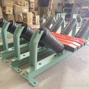
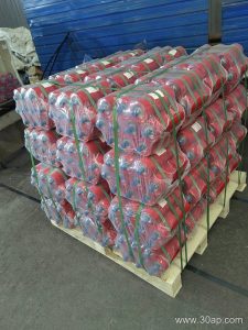
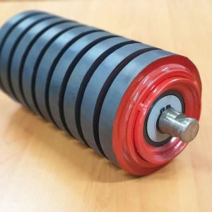
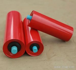
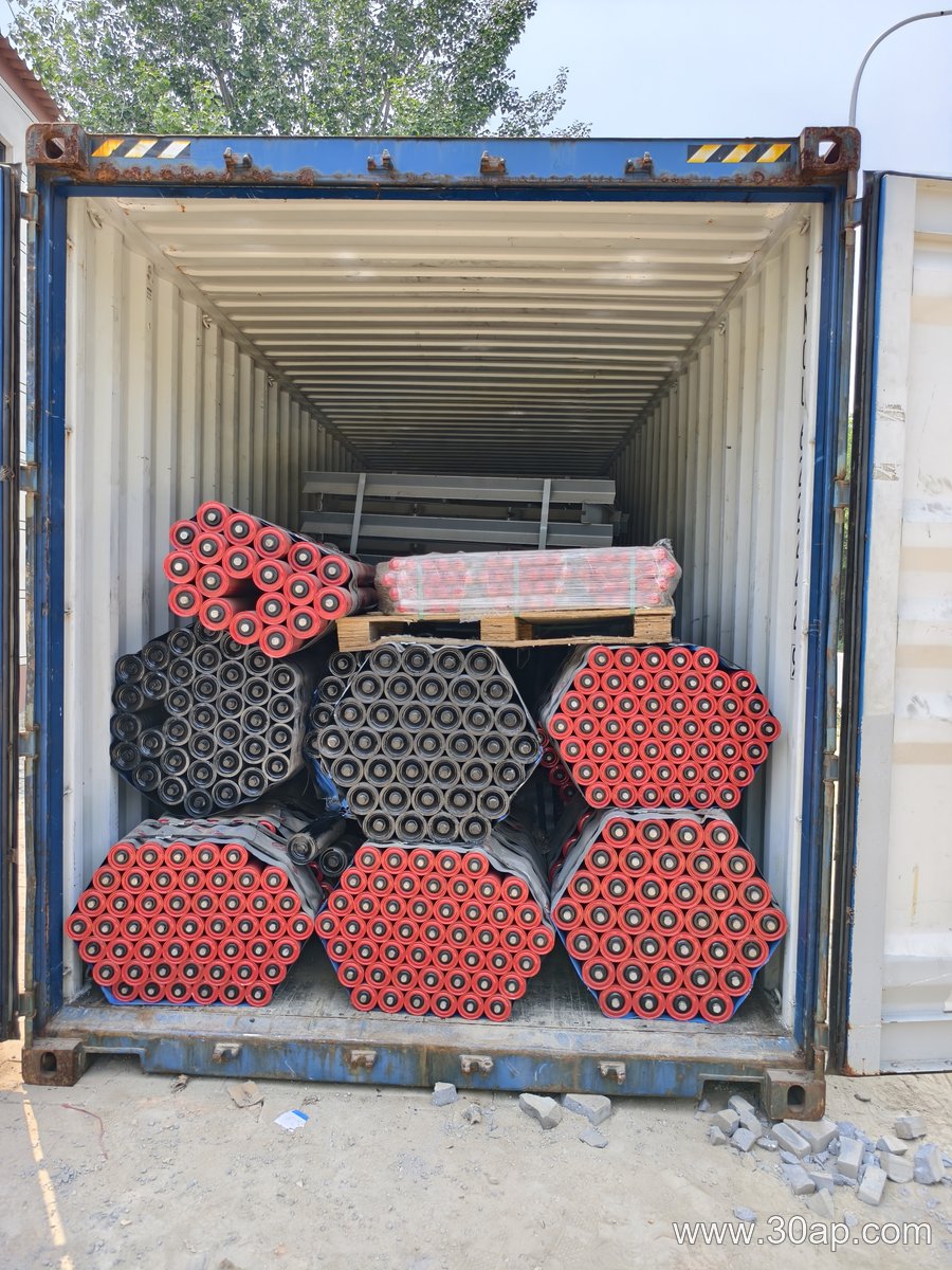
In a mineral-processing plant, an idler roller supports the conveyor belt and the ore load. If you space idler rollers too far apart, the belt sags between them, causing spillage and premature wear. Space them too closely, and you waste money on extra rollers and brackets. The goal is to find a practical spacing that keeps belt sag within an acceptable limit while using a reasonable number of idler rollers.
The Sag-Based Spacing Formula (Hypothetical Example)
Assume a straight carrying run with a uniform ore load. A common rule of thumb is to limit belt sag to 2% of the idler roller spacing. The approximate relationship is:
- S = idler roller spacing (m)
- T = belt tension (N)
- w = weight per unit length of belt plus material (N/m)
- f = allowable sag fraction (e.g., 0.02)
For a simply supported span, the maximum sag is roughly S = (w × L²) / (8 × T). Setting sag equal to f × L gives L = (8 × T × f) / w. This is a simplified estimate; actual design should follow the conveyor manufacturer’s method and relevant standards.
Worked Example with Stated Assumptions
Suppose a hypothetical mineral-processing conveyor has:
- Belt plus ore weight, w = 500 N/m
- Belt tension at the point of interest, T = 20,000 N
- Allowable sag fraction, f = 0.02
Then L = (8 × 20,000 × 0.02) / 500 = 6.4 m. Under these assumptions, an idler roller spacing of about 6.4 m would meet the 2% sag limit. In practice, you would round down to a standard spacing, such as 6 m, to provide a margin.
Belt Length and Idler Roller Count
Once spacing is chosen, the number of idler rollers on a straight carrying run is approximately N = run length / spacing, rounded up. For a 120 m run and 6 m spacing, N = 20 idler rollers. This count excludes transition zones and impact areas, where spacing is often reduced.
Always verify the final idler roller layout against actual belt tension, load distribution, and the manufacturer’s recommendations. The numbers here are illustrative only and should not replace a full engineering calculation.
Conveyor Pulley Sizing: A Design Trade-Off
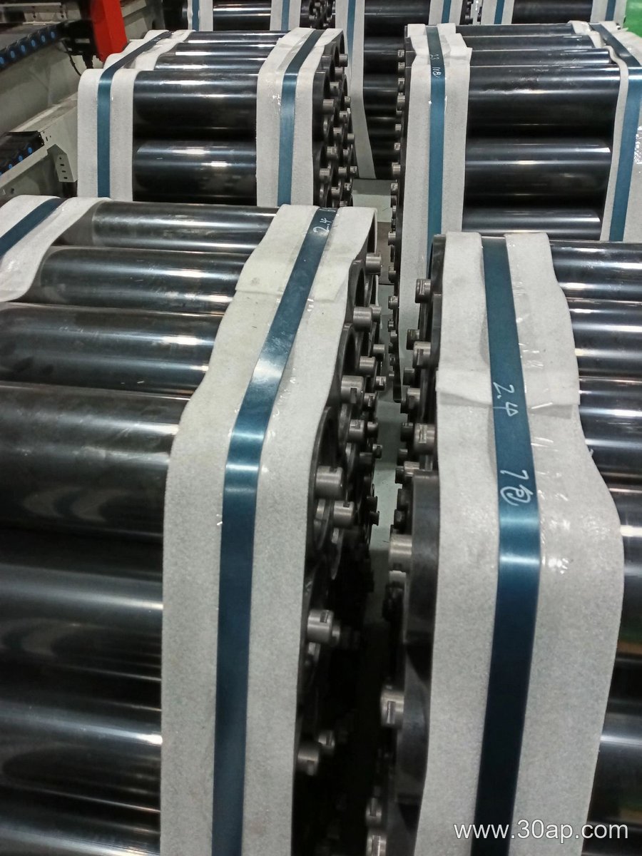
When specifying a conveyor pulley for a cement plant, engineers face a trade-off: a larger diameter reduces belt bending stress but increases torque and cost, while a narrower face saves space but may not accommodate belt tracking. A hypothetical example for a limestone belt illustrates the calculation.
Assumptions and Units
Assume a conveyor pulley with a belt tension of 50 kN on the tight side and 20 kN on the slack side, a wrap angle of 180°, a belt width of 1200 mm, and a belt thickness of 15 mm. The pulley face width must exceed the belt width by at least 100 mm to allow for misalignment. The minimum pulley diameter is often set by the belt manufacturer to limit bending stress; a common rule is that the pulley diameter should be at least 100 times the belt thickness for fabric belts, but for steel-cord belts, a larger ratio may apply. Here, using a hypothetical minimum diameter of 800 mm.
Calculating Face Width
Face width (FW) = belt width + 2 × (edge clearance). With a 50 mm clearance per side, FW = 1200 + 100 = 1300 mm. This ensures the belt remains supported even if it drifts slightly.
Calculating Diameter from Belt Tension
The required diameter can be checked against the allowable belt bending stress. A simplified method uses the belt’s minimum pulley diameter recommendation. For a hypothetical steel-cord belt with a recommended minimum diameter of 800 mm, that value governs. If no recommendation exists, a rough estimate uses the belt tension and allowable pressure on the pulley shell. For a pulley with a 180° wrap, the resultant force on the shaft is approximately the vector sum of tensions: sqrt(50² + 20²) ≈ 54 kN. This force, along with the pulley weight, determines shaft and bearing size, not the diameter itself. Diameter is primarily set by belt bending limits and the required torque transmission.
Torque and Power Check
Torque (T) = (T1 – T2) × radius. With T1 = 50 kN, T2 = 20 kN, and radius = 0.4 m (for 800 mm diameter), T = 30 kN × 0.4 m = 12 kN·m. This torque must be within the pulley’s design capacity, which depends on the shaft, hubs, and locking elements. In a cement plant, abrasive dust may require additional consideration for lagging and sealing, but the sizing calculation remains the same.
Practical Notes
- Always verify the minimum pulley diameter with the belt supplier; the 100× thickness rule is a starting point, not a universal specification.
- Face width should be at least belt width plus 100–200 mm for tracking.
- For high-tension applications, a larger diameter reduces belt stress but increases cost and space.
These calculations are hypothetical and for illustration only. Actual designs must follow applicable engineering standards and manufacturer data.