What the Head Pulley Assembly Does
The head pulley assembly is the drive end of a belt conveyor, the point where the belt discharges its load and where the motion is usually introduced. It combines a large conveyor pulley, its shaft, bearings, bearing housings, lagging and the supporting frame into one working unit. In a quarry or a sand and gravel line, this is the component that pulls the loaded belt uphill and releases material into the next screen or crusher. Because it carries the full belt tension, the assembly is built heavier than most other pulleys on the same conveyor.
The same unit is also called a drive pulley assembly or a head drum assembly. Those names describe the same product. A tail pulley, a bend pulley and a take-up pulley are different positions with different duties and are not substitutes for the head end.
How the Assembly Is Built
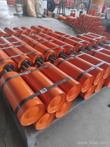
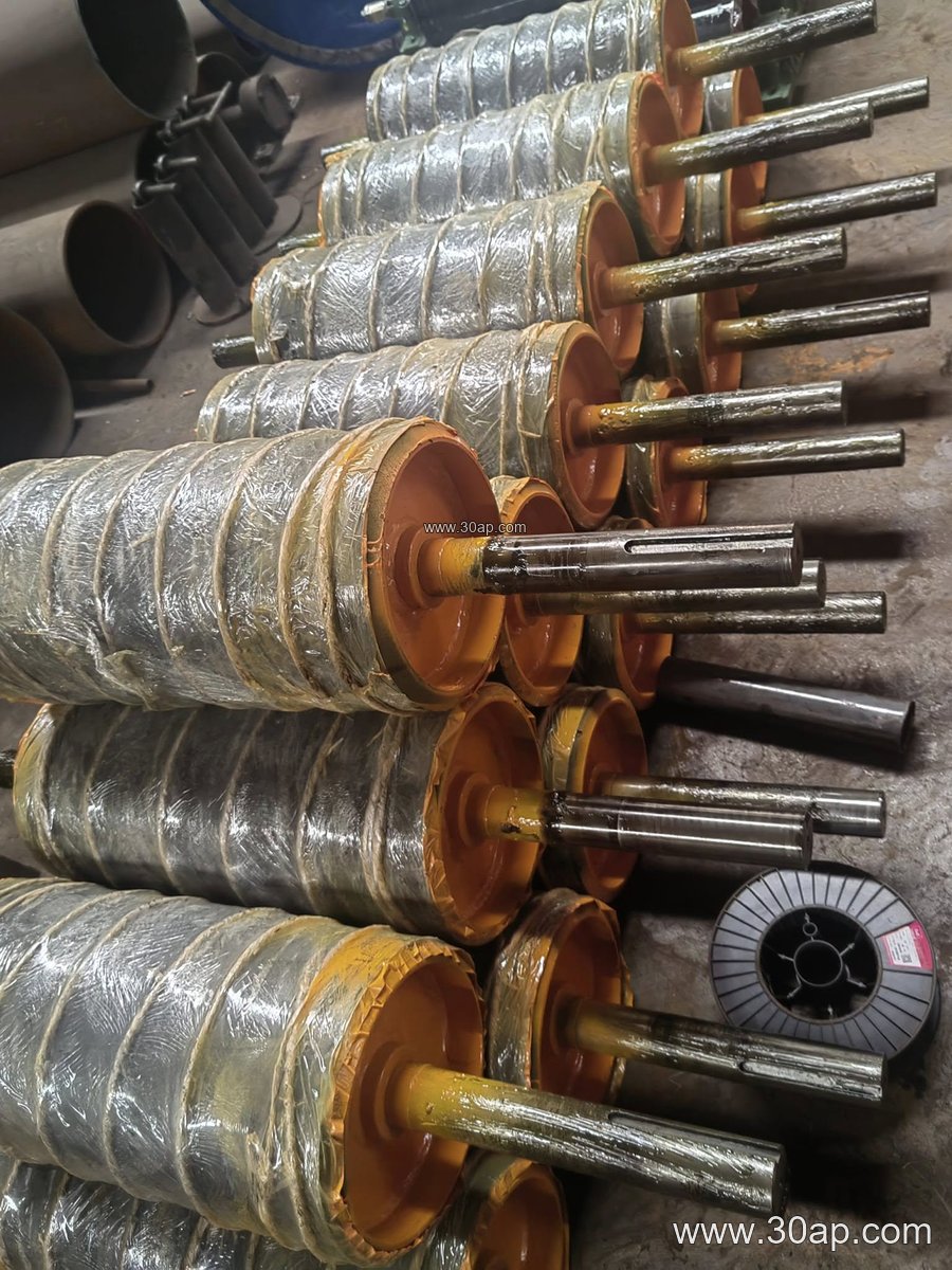
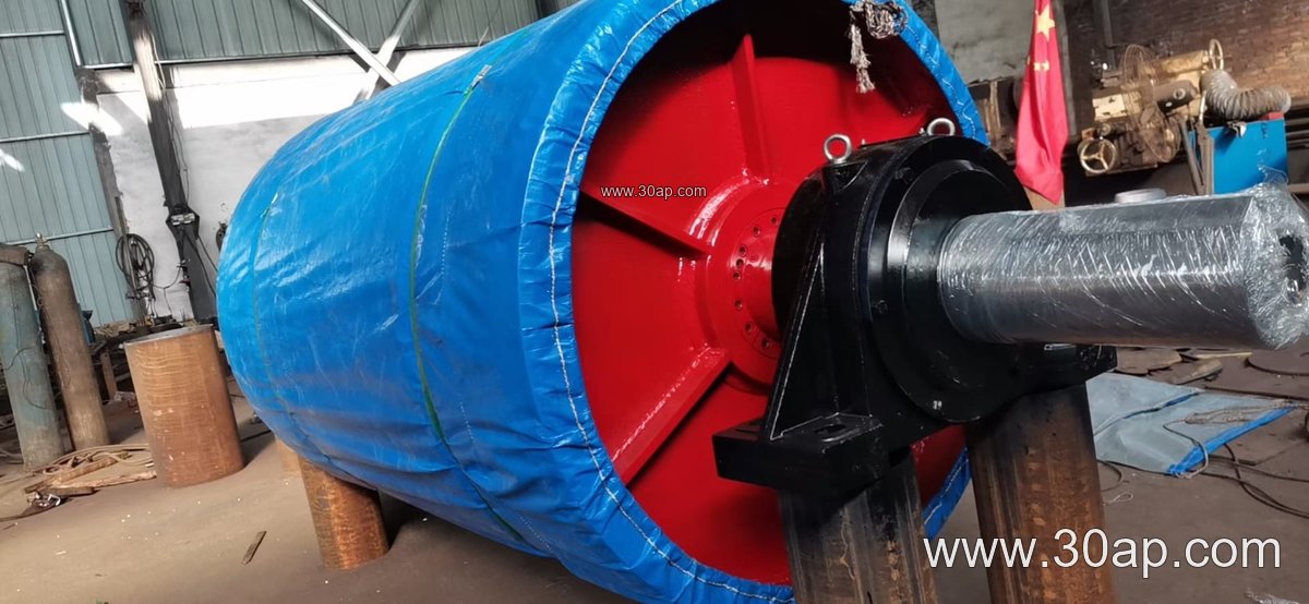
A typical assembly starts with a cylindrical shell, usually welded steel, with end discs and a hub. The shaft is keyed or shrink-fitted into the hubs and supported by spherical roller bearings in cast or fabricated housings. The whole unit sits in a conveyor bracket or frame that is bolted to the conveyor structure. Lagging is applied to the shell face to raise friction and protect the shell from wear.
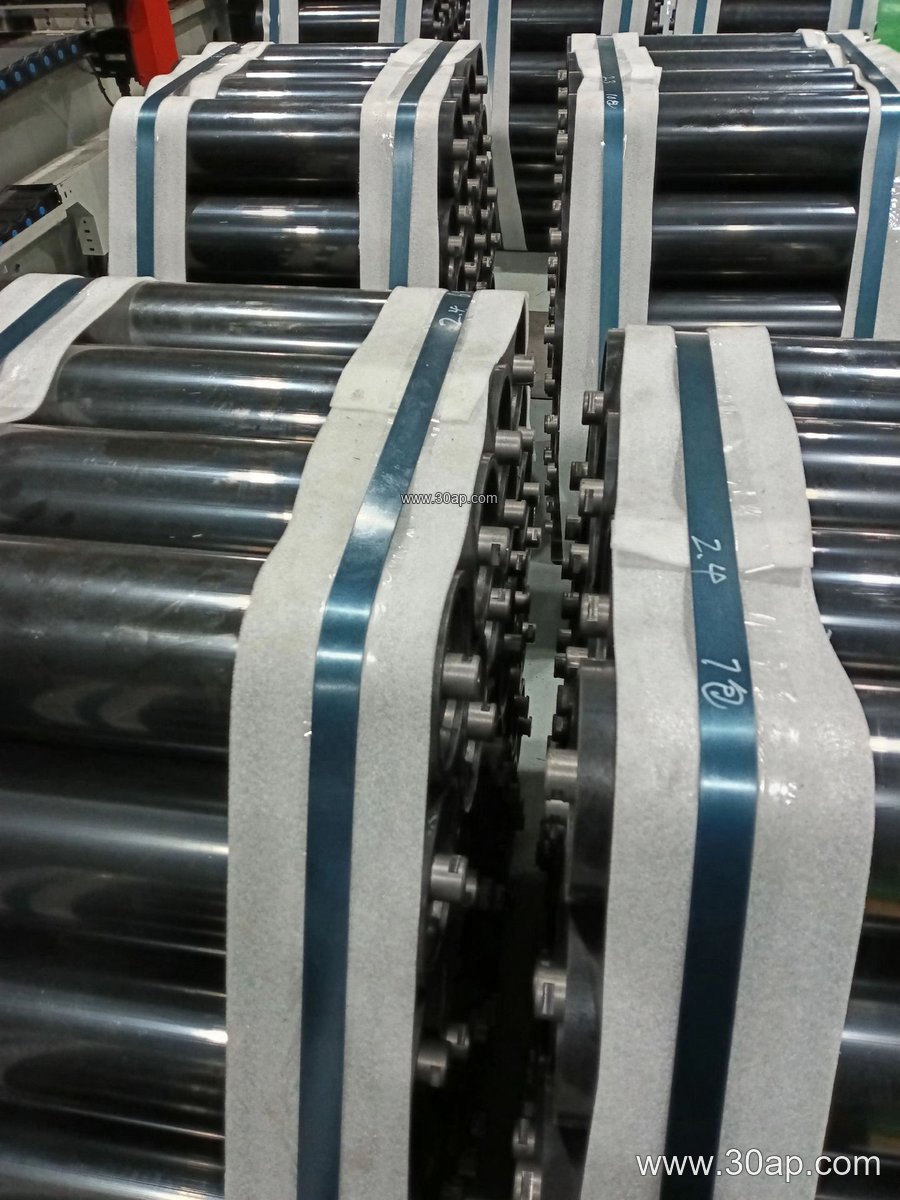
- Shell and end discs, welded and machined
- Through shaft with keyways, sized by torque and load
- Bearing housings with seals and lubrication points
- Lagging in plain, diamond, chevron or ceramic form
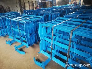
- Mounting frame or bracket matched to the conveyor stringer
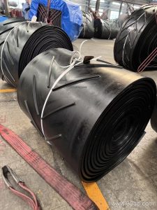
Lagging thickness is commonly 8, 10, 12, 15 or 20 mm depending on the duty. A rubber lagging gives good grip on an abrasion resistant conveyor belt; ceramic lagging is chosen where slip and wet conditions are a concern.
Sizes and Reference Data
Head pulley sizes are written as belt width against diameter, for example B800 x Ø500, B1200 x Ø1000 or B1400 x Ø800. The shell face is normally wider than the belt so the belt can track without rubbing the end discs. The table below gives common reference values, not fixed pairings.
| Belt width | Typical face width | Common diameters |
|---|---|---|
| B500 | about 600 mm | Ø250 to Ø400 |
| B650 | about 750 mm | Ø315 to Ø500 |
| B800 | about 950 mm | Ø400 to Ø630 |
| B1000 | about 1150 mm | Ø500 to Ø800 |
| B1200 | about 1400 mm | Ø630 to Ø1000 |
| B1400 | about 1600 mm | Ø800 to Ø1250 |
| B1600 | about 1800 mm | Ø1000 to Ø1400 |
| B1800 | about 2000 mm | Ø1250 to Ø1600 |
Shaft diameters commonly range from Ø50 up to Ø200, but the correct value comes from torque and bearing load calculations, not from belt width alone. A wide belt can run on a comparatively small diameter where tension is low, and a narrow high-tension belt may need a larger shaft.
Where It Is Used
In a coal preparation plant the head pulley assembly often runs with a flame retardant conveyor belt and anti-static lagging. In a cement plant it handles clinker on a heat resistant conveyor belt and may sit close to a discharge chute, so sealing and bearing protection matter. Portable crushing and screening plants use compact head units on short conveyors, while port bulk terminals use large diameter drums to reduce belt bending stress on long runs.
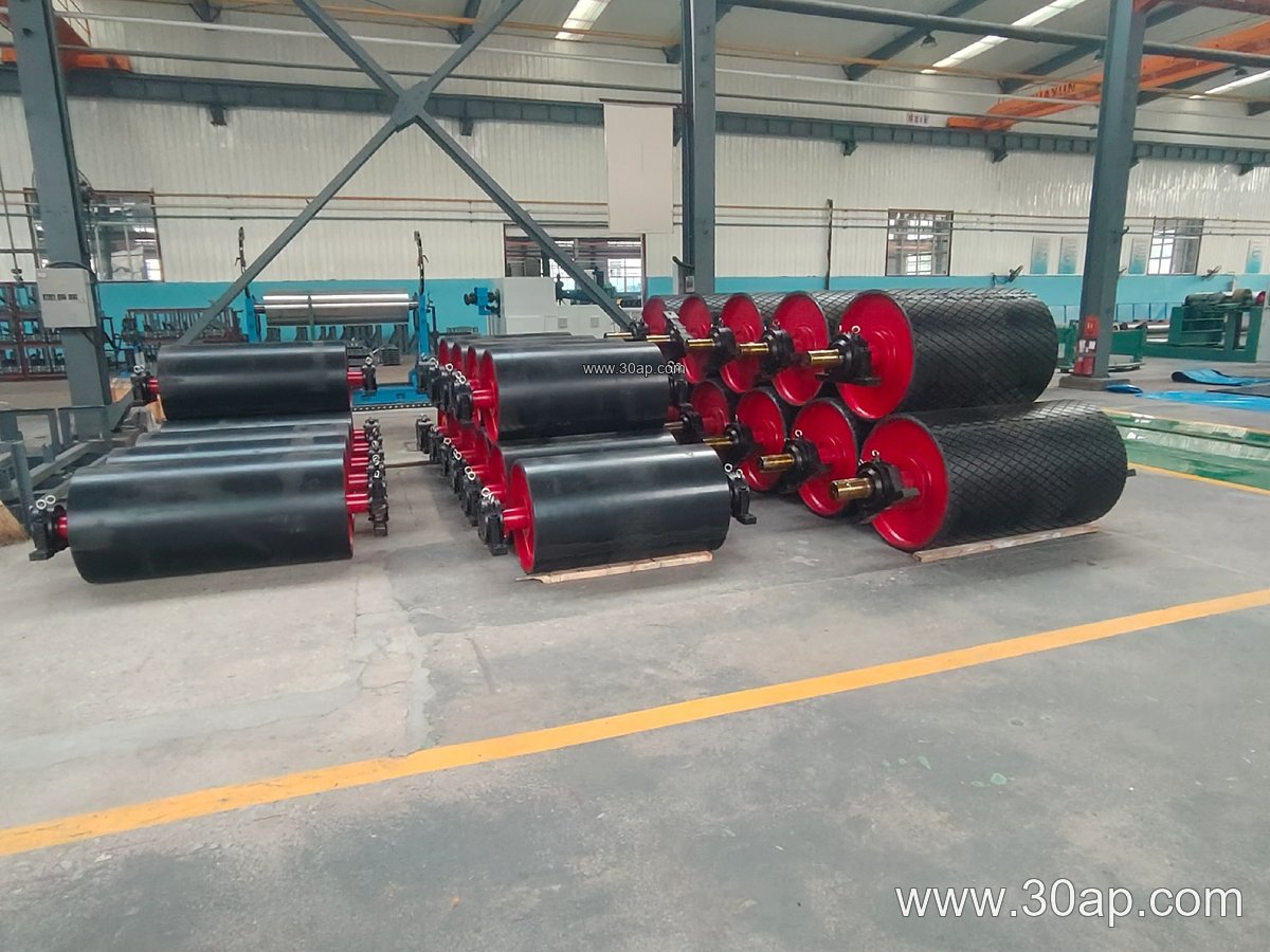
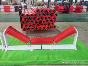
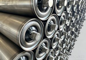
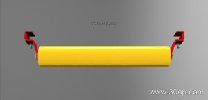
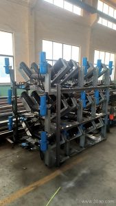
Whatever the site, the head end works together with the conveyor belt, the idler rollers along the carry side and the return side, and the conveyor bracket that holds the bearings. Alignment between these parts determines belt tracking more than any single component.
Buyer Checklist
- Confirm belt width and required face width, not just the nominal pulley size.
- State the duty: bulk density, lump size, throughput and hours per day.
- Choose lagging by condition, plain or diamond rubber for dry abrasive material, ceramic for wet slip risk.
- Ask for the shaft and bearing calculation basis rather than assuming a diameter.
- Check the mounting bracket dimensions against the existing conveyor frame.
- Plan lubrication access and a spare lagging kit before installation.
For a replacement unit, measure the old shell diameter, face width, shaft ends and bearing centre distance. A head pulley assembly that matches those dimensions avoids structural rework and keeps the conveyor running with its existing belt and idlers.