What a Conveyor Leg Does on a Belt Line
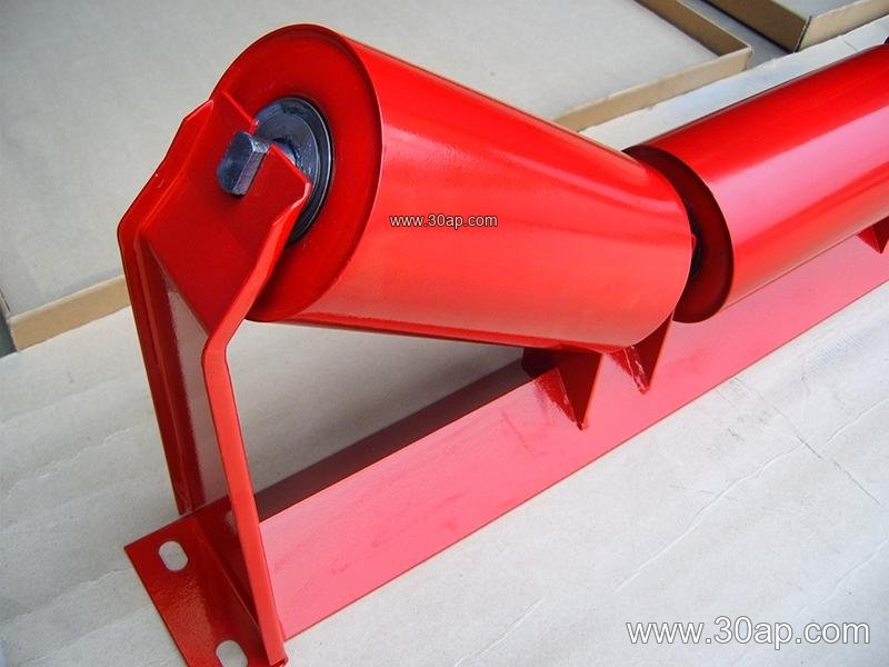
A conveyor leg is the vertical support element that carries the weight of the idler frames, the conveyor belt, and the material load down to the floor or foundation. In a typical troughing arrangement, the leg pairs with a cross beam to form a complete bracket assembly, and the idler roller sits in the cradle created by that assembly. Without properly sized legs, the whole structure flexes, the belt misaligns, and spillage increases. This is why the conveyor leg is treated as a structural component rather than a simple accessory in quarry, cement, power plant, and bulk handling installations.
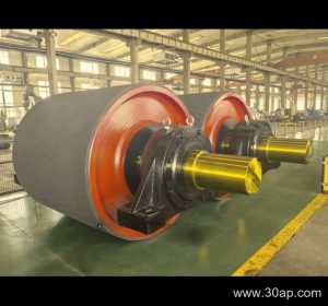
The same support element is often described as a belt conveyor support stand or a conveyor frame leg, and those terms refer to the same product. It should not be confused with a drive pulley, tail pulley, or bend pulley, which are rotating drum components that transmit or redirect belt motion and are not interchangeable with support legs.
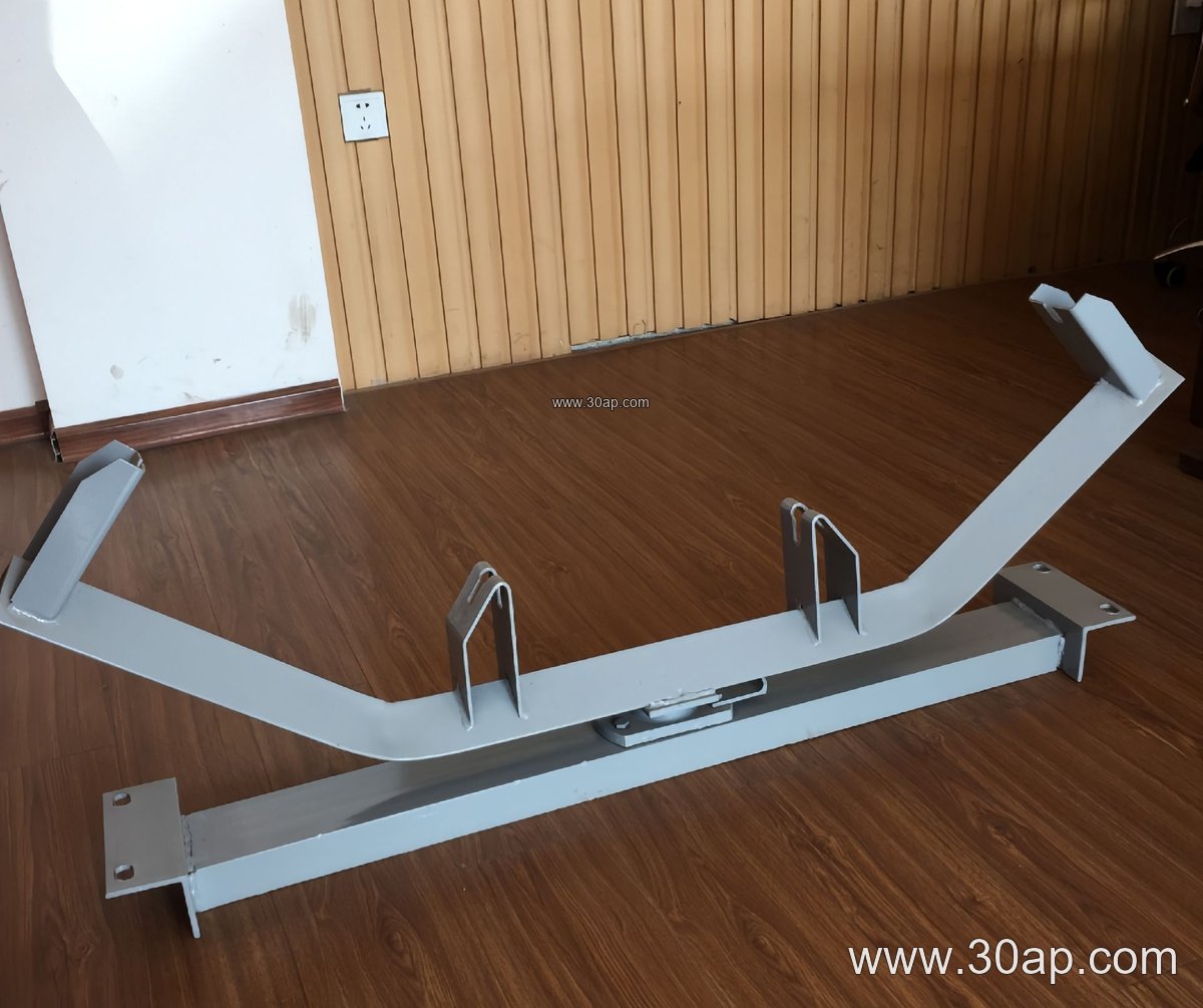
How the Support Frame Is Built
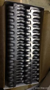
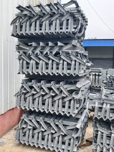
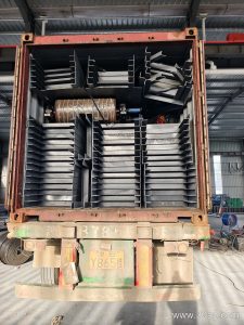
Most legs are fabricated from angle steel, channel steel, or folded steel plate. The choice depends on load, span, and the required stiffness. A common design uses two vertical posts joined by a top plate or gusset, with slotted or drilled holes that accept the cross beam. Slots allow small height adjustments during installation, which helps when the foundation is not perfectly level.
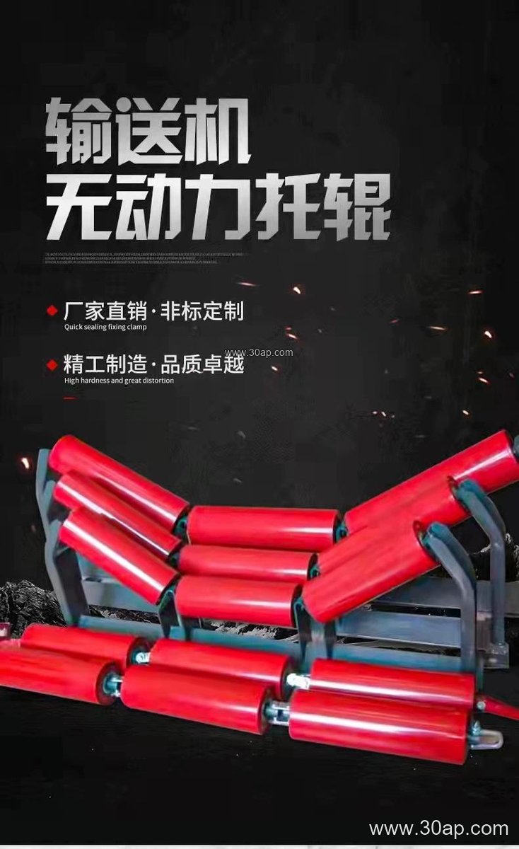
Fixed stands and adjustable stands differ mainly in how the idler frame is positioned. Adjustable units let maintenance crews fine-tune trough angle or belt contact without cutting and re-welding. Fixed units are simpler and often preferred in permanent crusher and screening lines where geometry does not change.
Typical Frame and Idler Reference Data
The table below lists reference values commonly discussed when matching a conveyor leg to a belt width and idler roller. These are reference data, not verified universal specifications, and final dimensions are confirmed by design.
| Belt width | Trough angle | Idler diameter | Typical leg material |
|---|---|---|---|
| B500 | 20 to 30 degrees | Ø89 | Angle steel |
| B650 | 30 degrees | Ø89 | Angle steel |
| B800 | 30 to 35 degrees | Ø108 | Channel steel |
| B1000 | 35 degrees | Ø108 or Ø133 | Channel steel |
| B1200 | 35 to 45 degrees | Ø133 | Folded plate |
| B1400 | 35 to 45 degrees | Ø133 or Ø159 | Folded plate |
| B1600 | 45 degrees | Ø159 | Folded plate |
| B1800 | 45 degrees | Ø159 or Ø194 | Heavy channel |
| B2000 | 45 degrees | Ø194 | Heavy channel |
| B2200 | 45 degrees | Ø194 | Heavy channel |
Several combinations are valid for the same belt width. A B1200 line may run 35 degrees with Ø133 rollers, or 45 degrees with a wider cradle, depending on material angle of repose and capacity. No single trough angle should be treated as mandatory for a given width. Installation hole spacing and cross beam length usually change with belt width and trough angle, so they should be confirmed against the drawing rather than assumed.
Where These Supports Are Used
In a limestone quarry, conveyor legs carry the loaded run through the crushing and screening section, where dust and shock loads are constant. In a coal handling system at a power plant, the same stands support the belt on the incline approaching the transfer tower, and here the legs are often paired with a flame retardant conveyor belt and a sturdy idler roller set. Designers sometimes choose a corrugated sidewall conveyor belt or a chevron conveyor belt on steep sections, and the support geometry must then account for the taller belt profile and the additional clearance it needs.
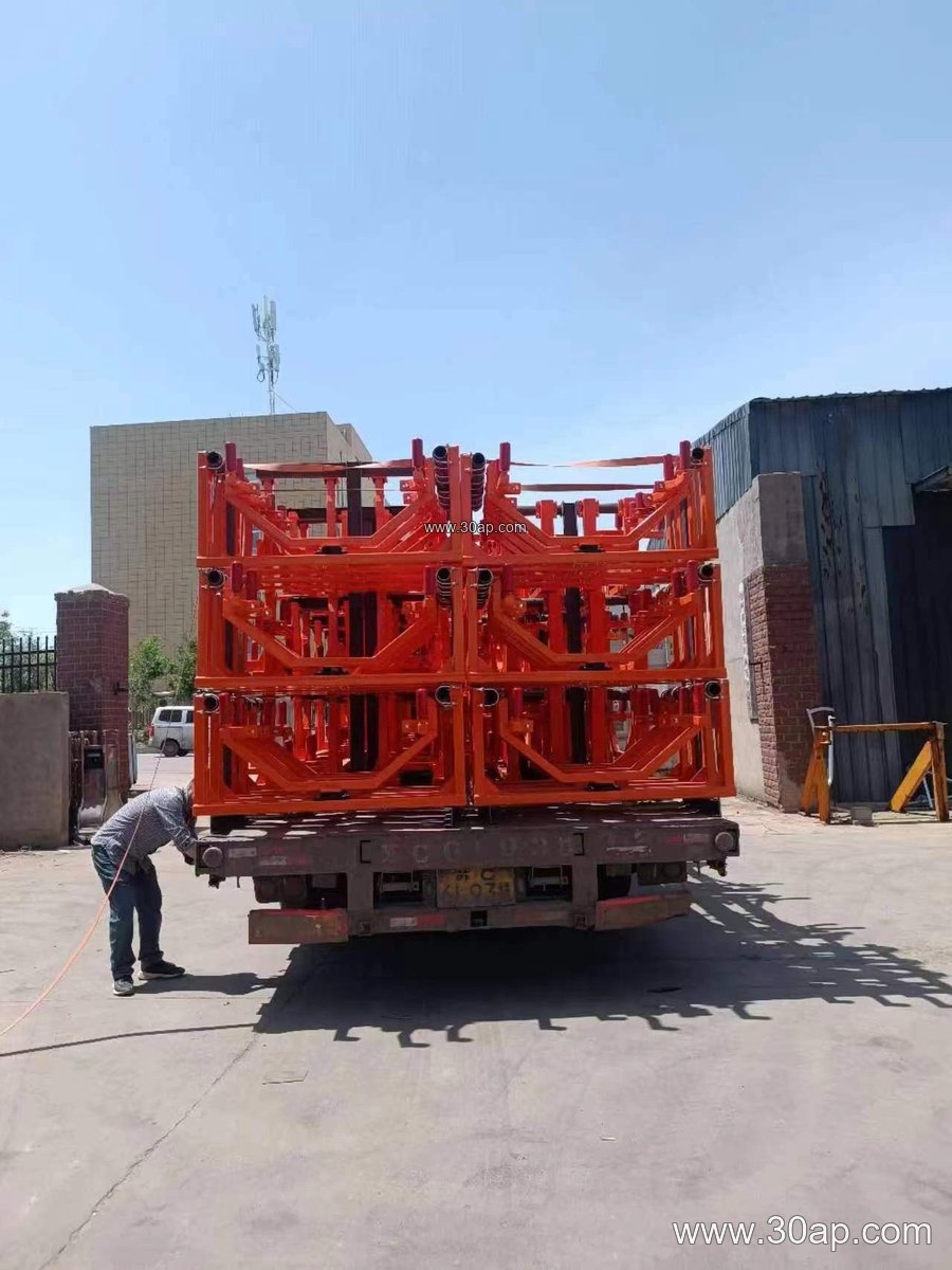
The support stand also appears in cement plants, steel sintering lines, fertilizer granulation halls, and grain silos. In each case, the local environment dictates coating, drainage, and bolt protection more than the basic shape of the leg.
Buyer Checklist Before Ordering
- Confirm belt width, trough angle, and idler diameter as a set, not in isolation.
- State whether the stand is fixed or adjustable, and the adjustment range required.
- Provide the cross beam hole pattern or ask the supplier to match the existing conveyor bracket.
- Describe the environment, such as wet washing areas or dusty coal yards, so surface treatment can be specified.
- Check that legs on the inclined section are tall enough to keep the belt clear of the ground after loading sag.
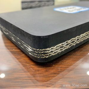
For a quick sanity check on load per leg, engineers often use P = (qb + qm) x g x L / 2 as a starting estimate, then apply a safety factor. The result guides steel selection but does not replace a full structural review. Whether the line carries an EP conveyor belt, an NN conveyor belt, a steel cord conveyor belt, or a heavy-duty mining conveyor belt, the support frame must be matched to the actual belt tension and material weight. More details on compatible frames and rollers can be found at conveyorleg.com and through our conveyor pulley and idler roller references.
Installation and Maintenance Notes
Set the first leg on each side of the line, then string a line to keep heights consistent before tightening anchor bolts. Check that the stand is square to the belt centerline, because a skewed leg twists the frame and pushes the belt toward one edge. During routine inspections, look for loose bolts, bent posts, and corrosion at the base plate. Replacing a damaged conveyor leg early is far cheaper than replacing the idler roller and belt section that misalignment damages later.