What a Guide Idler Bracket Does
A guide idler bracket is the mounting component that holds a guide idler in position along a conveyor frame. In practice, the term often refers to a bracket used with self-aligning or training idlers that keep a conveyor belt centered on the pulley line, but it can also describe a bracket that guides idler rollers into the correct trough angle at a transition point. Because conveyors in a quarry, a coal preparation plant, or a cement kiln feed line all suffer from belt wander in their own way, the guide idler bracket is a small part that protects a much larger investment in belting and structure.
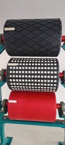
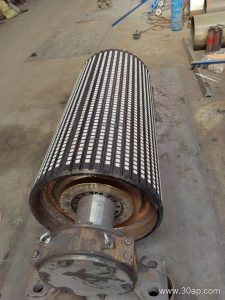
The bracket is not a pulley. A drive pulley, a tail pulley, and a bend pulley each turn with the belt and transmit or redirect tension, while a bracket stays fixed to the frame and supports the rotating idler roller. Confusing these parts leads to the wrong spare being ordered and to downtime that could have been avoided.
How the Bracket Is Built
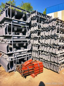
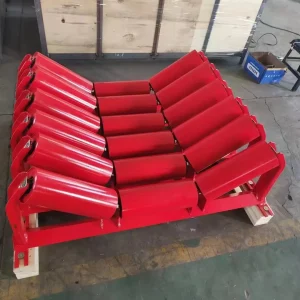
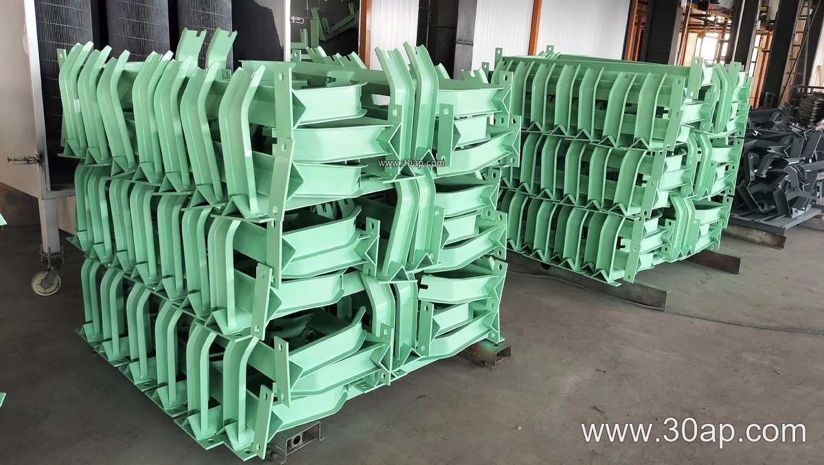
Most guide idler brackets are fabricated from angle steel, channel steel, or bent steel plate. The fabrication matters because the bracket must resist vibration, carry the weight of the idler and belt, and keep its position over years of service. A typical unit includes a base plate or clamp that bolts to the conveyor stringer, an upright arm or gusseted plate, and a slotted or drilled mounting face where the idler shaft sits.
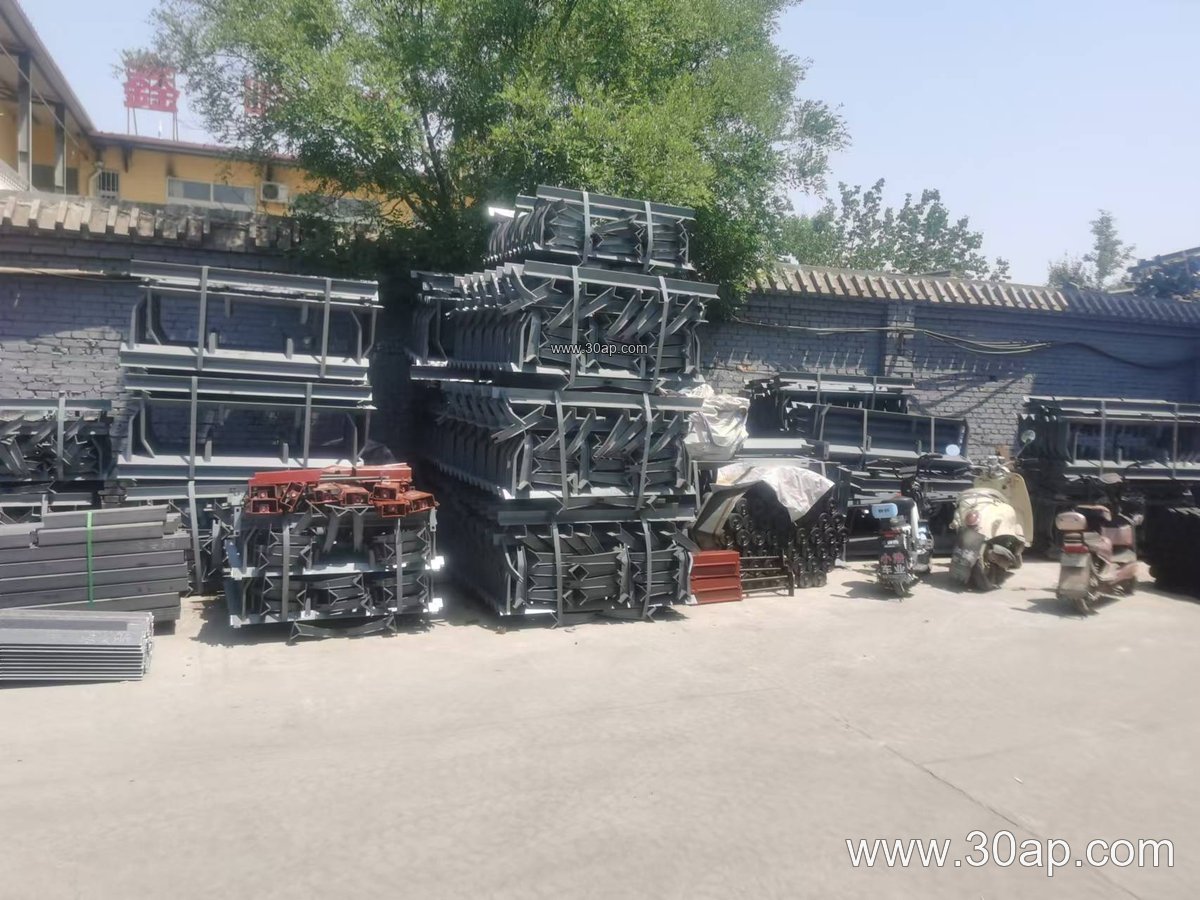
- Base connection: bolted clamp, welded pad, or hook arrangement
- Adjustment: slotted holes, shims, or a pivoting link for angle setting
- Mounting face: holes sized to the idler shaft and bearing housing
- Finish: painted or galvanized steel for dusty and humid conditions
Adjustable versions let maintenance staff change the bracket angle without cutting or re-welding the frame. Fixed versions are simpler and cheaper, and they suit lines where the belt path is already stable. Neither type is universally better; the choice depends on whether the belt needs periodic re-training.
Where It Fits on the Conveyor
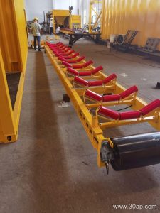
Guide idler brackets appear mainly on the carrying side, often just ahead of a loading point or after a curve, where the belt is most likely to drift. In a crusher discharge line feeding a screen deck, a pair of guide brackets can hold the training idlers that nudge the belt back to center before it reaches the head pulley. In an underground coal mining conveyor, the same bracket may be mounted on a compact frame where space is tight and dust is heavy.
The bracket should be matched to the trough angle and belt width it serves. Common trough angles for carrying idlers are 20, 30, 35, and 45 degrees, and adjustable brackets can move between these settings. A B800 frame at 35 degrees with Ø108 idlers is a familiar combination, while a wider B1200 line might run 45 degrees with Ø133 rollers. These are examples, not rules: the correct match depends on belt width, material lump size, and the load the idler must carry.
| Reference Item | Common Range | Notes |
|---|---|---|
| Belt width (B) | B500 to B2200 | Bracket length and hole spacing vary with width |
| Trough angle | 20 to 45 degrees | Adjustable brackets cover several settings |
| Idler diameter | Ø89 to Ø194 | Selected by load and belt speed |
| Forward tilt | About 1.5 to 2 degrees | Used on training idlers, not all brackets |
Working With Belt and Idler Selection
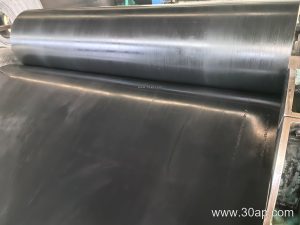
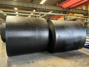
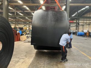
The bracket is only as good as the components around it. A heavy-duty mining conveyor belt carrying iron ore needs sturdy idler rollers and brackets that hold alignment under shock loading, while a food grade conveyor belt in a grain silo may need smooth, cleanable surfaces and lighter brackets. On long overland lines, a steel cord conveyor belt may be paired with training idlers on guide brackets to control lateral movement over distance. In cement plants, heat resistant conveyor belt sections near the kiln discharge still rely on correctly set brackets to keep the belt from rubbing the frame.
When specifying, check the shaft diameter of the idler, the bolt hole pattern on the stringer, and the clearance needed for the belt edge. Do not assume that one belt width corresponds to one pulley diameter or one trough angle. The bracket should be ordered against the actual frame drawing, and installation hole spacing should be confirmed by measurement rather than by a generic table.
Buyer Checklist and Maintenance
- Confirm whether the bracket is fixed or adjustable and how the angle is locked.
- Match the mounting holes to the idler shaft and bearing housing.
- Check steel thickness and finish for the site environment.
- Verify bolt spacing against the existing stringer before ordering.
- Inspect for loose bolts, bent arms, and worn slots during routine walks.
A loose guide idler bracket can allow the idler to shift, which then wears the belt edge and loads the pulley faces unevenly. Regular checks during shutdowns in a power plant coal yard or a sand and gravel line cost little and prevent belt damage. For operators sourcing replacement parts, a clear drawing of the bracket and a note on the conveyor duty are more useful than a guessed part number.