What Conveyor Pulley Welding and Machining Involves
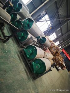
Conveyor pulley welding and machining are the two critical fabrication stages that turn steel components into a reliable drive, tail, or bend pulley. Welding joins the shell, end discs, and hub into a single load-bearing unit, while machining brings the shaft bore, face, and mounting surfaces to the required fit and finish. For anyone specifying a conveyor pulley for a quarry, coal mine, cement plant, or power station coal yard, understanding these processes helps in evaluating durability and lead time.
Step-by-Step Fabrication
Production typically starts with cutting and rolling the shell to the required diameter and face width. End discs are prepared with bores for the shaft or hub. Welding then proceeds in a controlled sequence to minimize distortion: longitudinal seam first, followed by circumferential welds joining discs to the shell, and finally hub-to-disc connections. After welding, the assembly is stress-relieved when specified. Machining comes next: the shaft bore is bored and keyed, the outer face is turned or ground for concentricity, and end faces are squared to the axis. The finished pulley is balanced and, if required, coated or lagged.
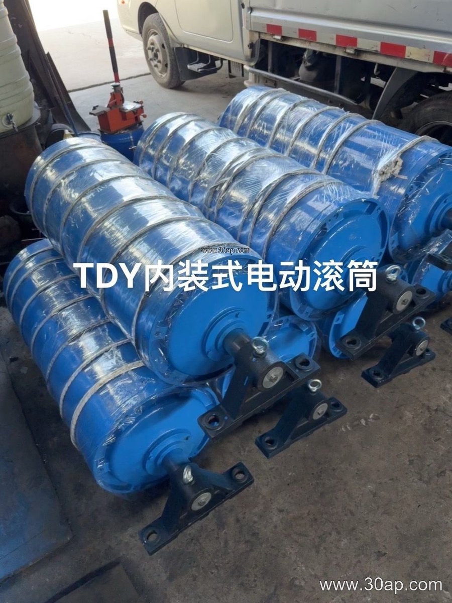
Why Machining Accuracy Matters
Machining tolerances directly affect bearing life and belt tracking. An out-of-round shell or misaligned bore can cause vibration, premature lagging wear, and edge damage on the conveyor belt. For high-tension applications—such as a heavy-duty mining conveyor belt or a steel cord conveyor belt—the pulley face and shaft fit must be precise enough to handle continuous load without loosening. Common diameter ranges for conveyor pulleys run from Ø200 to Ø1800, and face widths usually exceed the belt width by about 100–200 mm; for example, a B1200 belt often uses a pulley face around 1400 mm. These are reference figures, not fixed rules.
Welding Quality and Inspection
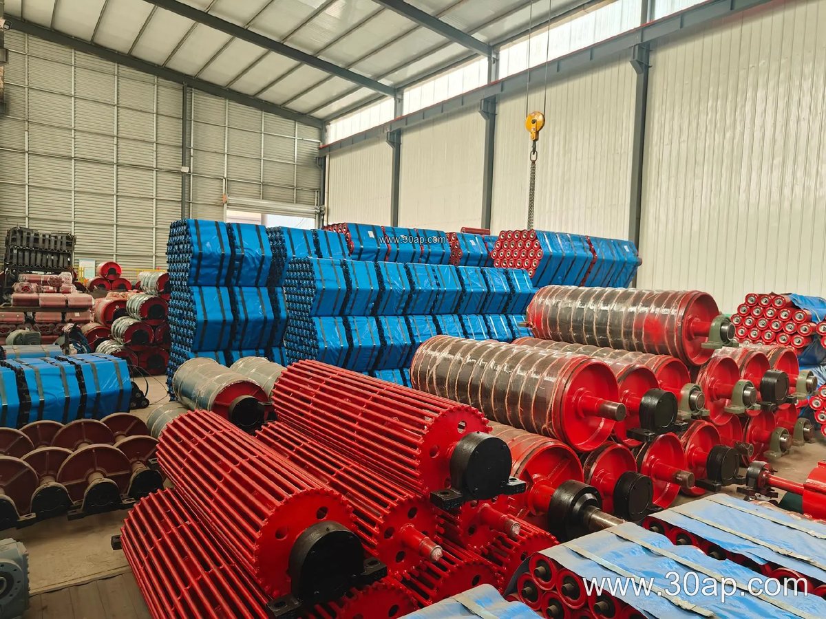
Weld quality determines whether a pulley can survive years of shock loading in a crusher discharge or tunnel mucking duty. Visual inspection, dimensional checks, and non-destructive testing (such as ultrasonic or magnetic particle inspection) are commonly applied to critical welds. Buyers should ask for weld procedure specifications and inspection records when the pulley is destined for a coal mining conveyor belt system or an iron ore conveyor belt line where downtime is costly.
Surface Preparation and Lagging
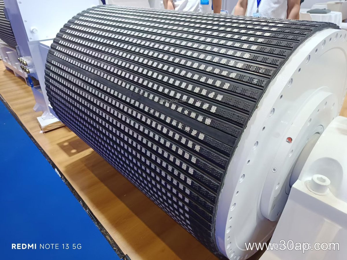
After machining, the pulley surface may be left plain or prepared for lagging. Common surface options include plain finish, hot-vulcanized rubber, cold-bonded rubber, diamond grooving, herringbone pattern, and ceramic lagging. Lagging thickness is often 8, 10, 12, 15, or 20 mm depending on grip requirements and material abrasiveness. A drive pulley handling wet, abrasive aggregate may benefit from ceramic or diamond lagging, while a bend pulley in a clean cement plant might use plain or lightly lagged finish.
Where These Pulleys Are Used
Welded and machined conveyor pulleys appear across bulk material handling: as drive pulleys at the head of a belt, tail pulleys at the loading point, and bend or take-up pulleys along the return run. In a limestone quarry, a Ø800 drive pulley might tension an EP conveyor belt carrying crushed rock; in a coal washing plant, a Ø630 tail pulley may guide a flame retardant conveyor belt through a wet, dusty environment. The same fabrication approach serves sand and gravel lines, fertilizer plants, and port ship-loading systems.
Buyer Checklist for Welded and Machined Pulleys
When sourcing, confirm the shaft diameter is sized by torque and load—not by belt width alone. Typical shaft diameters range from Ø50 to Ø200 mm. Check that the pulley face width matches the belt width with adequate margin, and verify lagging type and thickness against the material being conveyed. Also review welding documentation and machining tolerances for bore concentricity and face runout. For high-abrasion duties, consider pairing the pulley with an abrasion resistant conveyor belt and well-aligned idler roller sets to reduce wear on both components.
For more information on matching pulleys with conveyor belts and rollers, visit conveyor pulley and conveyor belt resources.