What Conveyor Bracket Fabrication Involves
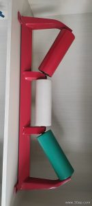
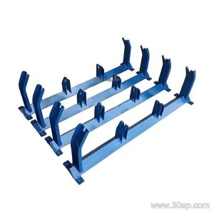
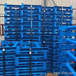
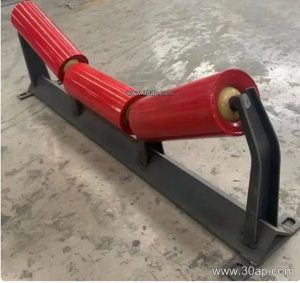
Conveyor bracket fabrication is the process of cutting, forming, drilling, and welding the steel frames that hold idler rollers in place along a conveyor line. These brackets, often called idler frames or roller supports, are the interface between the conveyor belt and the conveyor structure. A well-fabricated bracket keeps the idlers at the correct height and angle, so the belt runs true whether the system carries coal at a power plant or crushed stone at a quarry.
The work is part fabrication and part fit-up. A fabricator must respect the mounting hole spacing, the beam length, and the trough angle called out in the design, because small errors show up as belt misalignment and premature roller wear.
Materials and Build Method
Most brackets are built from angle steel, channel steel, or folded steel plate. The choice depends on load and span:
- Angle steel for lighter carrying idler supports and return frames.
- Channel steel for wider belts and heavier bulk material loads.
- Folded plate where a compact, stiff profile is needed.
Fabrication usually follows a simple sequence: shearing or laser cutting the stock, drilling or punching the idler mounting holes, bending the trough wings, then jig welding the assembly so that hole centres stay square. A drill jig or a fixture reduces distortion during welding, which matters because a twisted frame will tilt the rollers and steer the belt to one side.
Trough Angle, Belt Width, and Roller Diameter
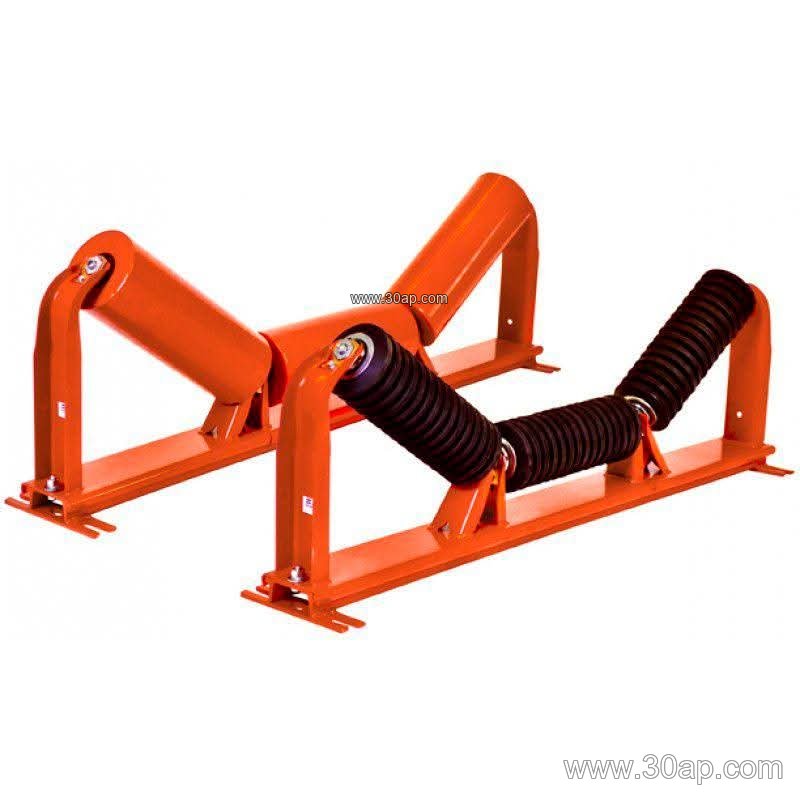
The bracket geometry is defined by three linked values: belt width, trough angle, and roller diameter. Common belt widths run from B500 through B2000 and beyond, while trough angles are typically 20, 30, 35, or 45 degrees. Adjustable brackets allow the same frame to be set at several of these angles during installation.
Roller diameters commonly used with these frames include Ø89, Ø108, Ø133, Ø159, and Ø194. These values are not fixed pairings; a given belt width may work with more than one trough angle or roller diameter depending on capacity, material lump size, and transition requirements. The table below shows typical reference combinations, not mandatory matches.
| Belt Width | Typical Trough Angle | Typical Roller Diameter |
|---|---|---|
| B500 / B650 | 20–30 degrees | Ø89 / Ø108 |
| B800 / B1000 | 30–35 degrees | Ø108 / Ø133 |
| B1200 / B1400 | 35–45 degrees | Ø133 / Ø159 |
| B1600 / B1800 | 35–45 degrees | Ø159 / Ø194 |
Installation hole spacing and crossbeam length change with belt width and trough angle, so they should always be taken from the approved drawing rather than assumed.
Where These Frames Are Used
Fabricated brackets appear wherever a belt conveyor moves bulk material. In a coal handling system at a power plant, carrying brackets support the troughing idlers that shape a flame retardant conveyor belt into a stable trough. At a limestone quarry or aggregate plant, heavy-duty frames carry abrasion resistant conveyor belt over long distances. Similar frames serve cement plants, steel mills, port loading lines, and sand and gravel operations.
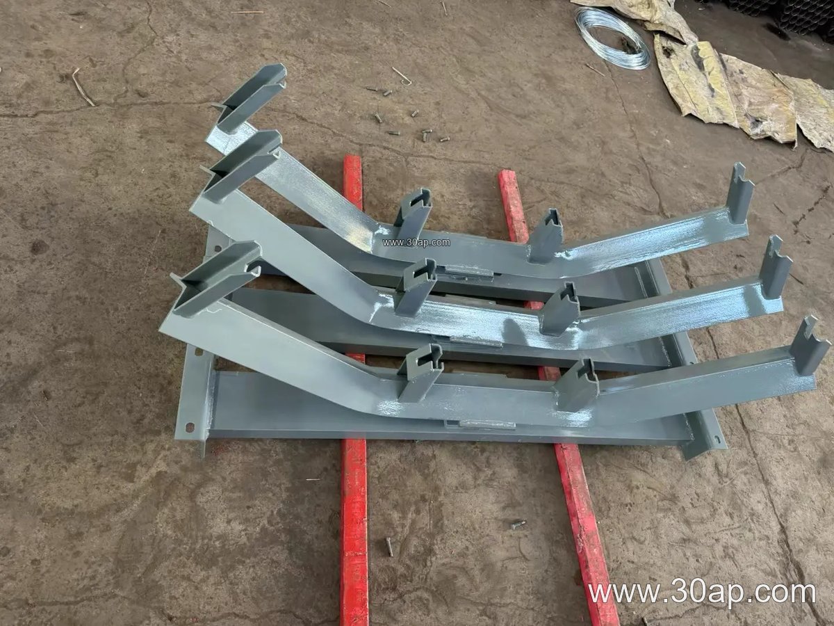
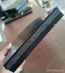
Because the bracket holds the idler roller, its accuracy directly affects belt tracking. A misaligned frame on the carrying side can cause edge damage on an EP conveyor belt or a steel cord conveyor belt, while a poor return bracket may let the belt sag and rub the structure.
Types a Buyer May Encounter
Fabrication covers several frame families, each with a distinct role:
- Carrying trough brackets and transition brackets near the pulley.
- Return brackets, including flat and V-shaped return frames.
- Impact brackets under loading points, often paired with impact idlers.
- Self-aligning and forward-tilted frames for tracking control.
- Suspended and adjustable frames for easy angle setting.
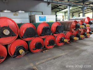
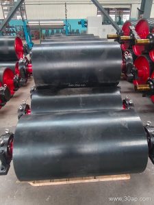
These are not interchangeable with drive, tail, or bend pulleys, which are separate components. A bracket only supports the idlers; it does not transmit drive torque.
Buyer Checklist
When ordering fabricated brackets, confirm the belt width, required trough angle, roller diameter, and mounting hole pattern. Ask for the steel profile and surface treatment, and check that the drawing shows the correct crossbeam length. For systems using a pipe conveyor belt or a corrugated sidewall conveyor belt, confirm that the frame clears the belt profile. Good fabrication practice, verified dimensions, and a clear drawing package keep the conveyor running straight and reduce maintenance downtime.