What Pulley Custom Machining Covers
Pulley custom machining is the engineering and fabrication work that turns a standard drum shell into a pulley matched to a specific conveyor layout. In practice, it means the drum diameter, face width, shaft, bearing arrangement, lagging surface and mounting details are all made to suit the belt width, the load and the position in the conveyor frame. A quarry line handling abrasive aggregate and a power plant coal conveyor rarely share the same pulley specification, so custom machining bridges that gap instead of forcing a catalogue part into a duty it was not designed for.
The product is usually called a custom conveyor pulley or bespoke conveyor drum. Both terms describe the same item: a machined drum assembly that carries the belt, transmits drive torque or changes belt direction. Drive, tail and bend pulleys are separate positions with different duties and should not be treated as interchangeable.
How a Custom Pulley Is Built
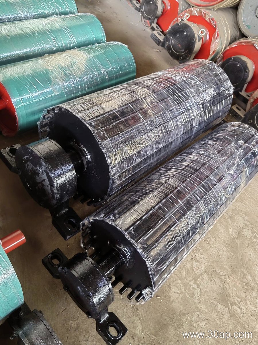
The shell is rolled from steel plate, welded to end discs, then machined so the outside diameter runs true. The shaft is turned to the required journal sizes, keyways are cut, and bearing housings are fitted. For a drive pulley, the hub-to-shaft connection and the lagging grip are critical because torque has to pass through the drum without slip.
Common reference dimensions in custom work include:
- Belt widths from B400 to B2400, with face widths typically running wider than the belt, for example about 1400 mm face for B1200 and about 1600 mm for B1400.
- Drum diameters such as Ø200, Ø315, Ø500, Ø800, Ø1000 and Ø1250, selected by belt tension and wrap angle rather than belt width alone.
- Shaft journals commonly in the Ø50 to Ø200 range, sized from torque and bearing load.
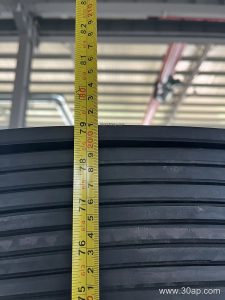
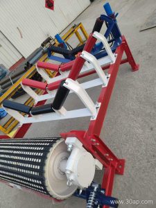
- Lagging options including plain finish, cold-bonded rubber, hot-vulcanised rubber, diamond grooving, chevron grooving and ceramic tiles, usually 8 to 20 mm thick.
No single belt width locks in one diameter or one shaft size. A B800 conveyor might use Ø500 in a short tail position and Ø800 at the head, depending on tension and belt speed. That is exactly why the machining drawing should follow the conveyor calculation.
Where the Machined Drum Fits
In a sand and gravel plant, a custom head pulley with diamond lagging drives a belt fed by a crusher, while the tail pulley runs plain or lightly lagged. In a cement plant clinker line, heat exposure and fine dust make bearing sealing and lagging choice more important than raw shell thickness. In coal handling, flame retardant and anti-static belt requirements often pair with pulleys that must resist build-up and misalignment.
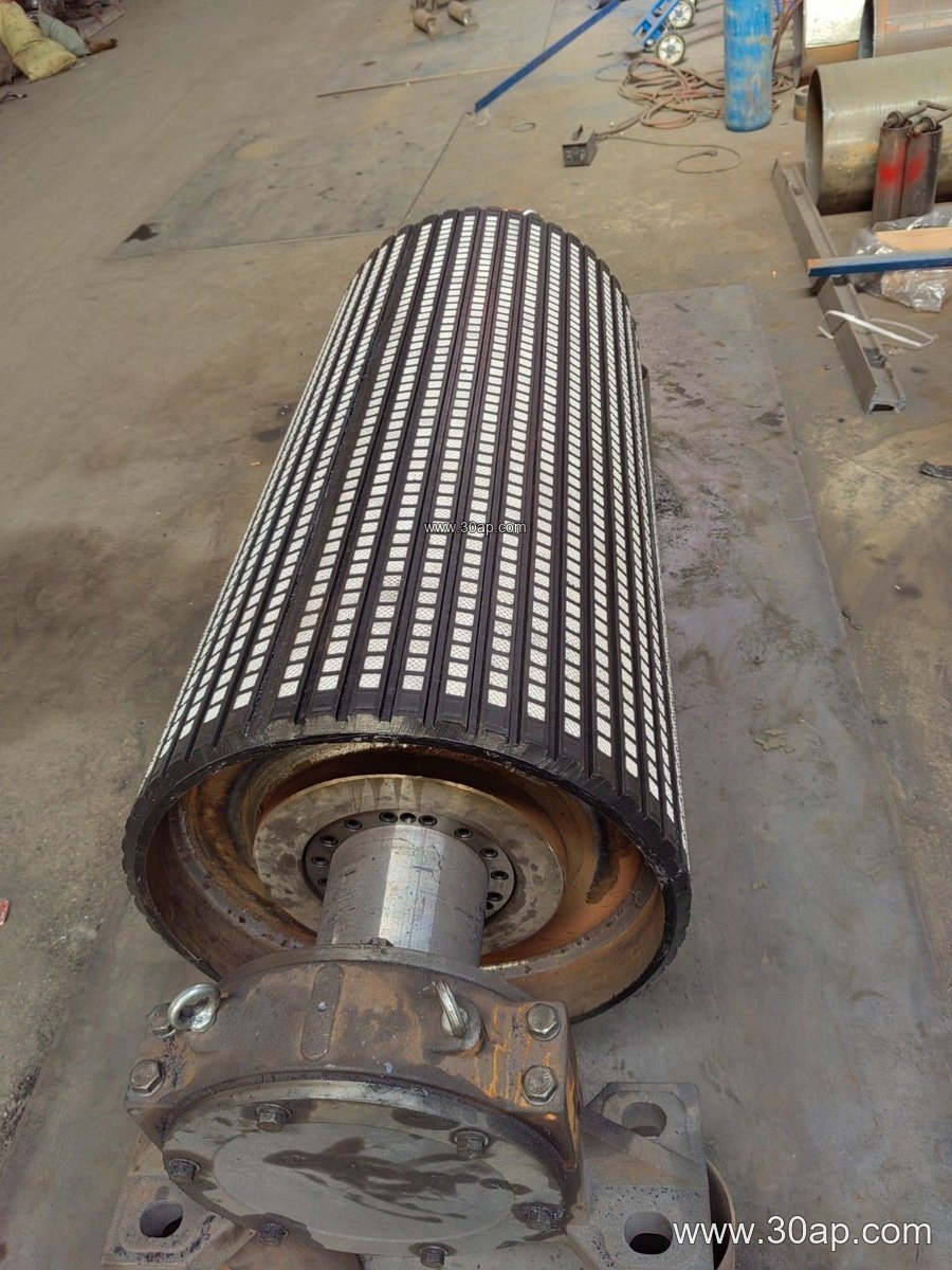
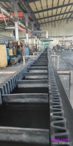
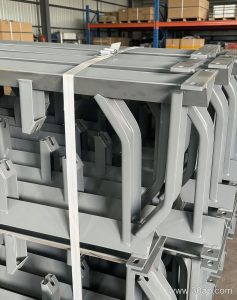
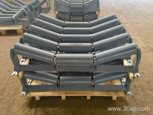
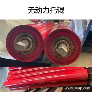
The drum does not work alone. It interacts with the conveyor belt, the idler roller set that supports the carry side, and the conveyor bracket that holds the bearing housing. A poorly matched bracket or a shaft that is undersized for the load will shorten bearing life no matter how good the shell is.
Buyer Checklist Before Ordering
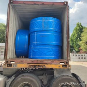
Provide the belt width, belt type and expected tension so the drum diameter and shaft can be calculated properly. State the position: drive, tail, bend, take-up or snub. Confirm the lagging surface and thickness, the bearing type, the shaft extension and any keyway detail. If the conveyor uses an EP conveyor belt or a steel cord conveyor belt, mention it, because elastic stretch and starting tension affect pulley grip and take-up travel.
Ask for the machining tolerance on diameter and runout, the balance grade for high-speed drums, and the surface protection for the environment. In a port or ship loading system, salt air may call for a different coating than an underground coal mine. These are design decisions, not catalogue defaults.
Machining Quality That Shows Up Later
A pulley that runs out of round will wear the belt edge and load the bearings unevenly. Weld quality, stress relief before final machining and accurate keyway cutting all matter. For heavy-duty mining conveyor duty, the shell-to-end-disc weld and the hub fit are the areas most likely to fail if shortcuts are taken. Custom machining should include inspection records for diameter, face width, shaft runout and lagging bond, and the drawing should be traceable to the conveyor duty it was made for.