What a Carbon Steel Conveyor Bracket Does
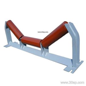
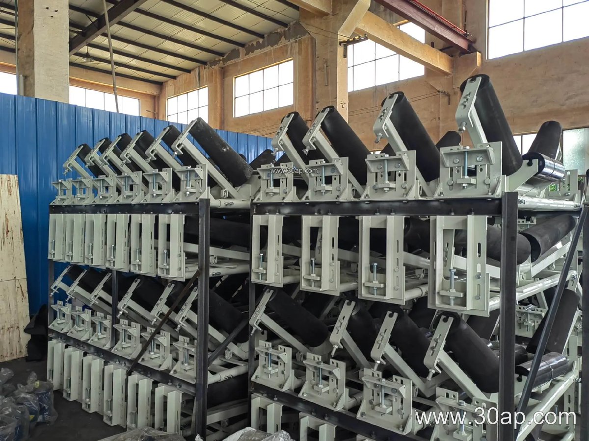
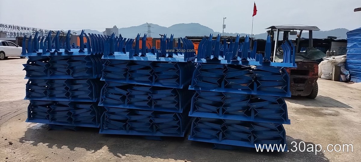
A carbon steel conveyor bracket is the structural support that holds idler rollers in position along a conveyor frame. It carries the weight of the loaded belt and keeps each roller at the correct angle and spacing so the conveyor belt tracks smoothly. In a quarry, a cement plant, or a power plant coal yard, these brackets are usually the least visible part of the system, yet they determine how evenly the belt is supported and how long the rollers last.
The bracket is typically fabricated from angle steel, channel steel, or folded steel plate. The grade of carbon steel is chosen for weldability and stiffness rather than for corrosion resistance, so in wet or dusty service a painted or galvanized finish is common. Mounting holes are punched or drilled to match the frame, and the crossbeam length is determined by the belt width and trough angle rather than by a single standard figure.
Common Bracket Arrangements on a Conveying Line
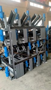
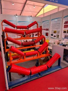
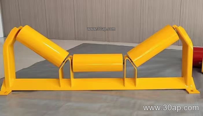
On the carrying side, a troughing bracket holds three idlers in a troughed profile. A transition bracket sits between the flat pulley approach and the full trough, gradually changing belt shape. On the return side, a flat return bracket or a V-return bracket supports the empty belt. Impact brackets with cushion rollers are placed under loading points, while self-aligning brackets help correct belt drift. Each of these is a distinct subtype, and they are not interchangeable in function or position.
- Troughing brackets carry the loaded belt, usually with 20, 30, 35, or 45 degree trough angles.
- Transition brackets control the belt as it opens from the pulley.
- Return brackets support the empty strand, flat or V-shaped.
- Impact brackets absorb shock below chutes and transfer points.
- Self-aligning brackets rotate slightly to steer a wandering belt.
Adjustable designs allow the trough angle to be set on site, which is useful when a conveyor line handles more than one material. Fixed brackets are simpler and stiffer but must be ordered to the exact angle.
Matching Bracket, Belt Width, and Roller Diameter
Selection starts with belt width and the roller diameter the frame can accept. Typical combinations seen in catalogues include B800 with a 35 degree trough and Ø108 rollers, or B1200 with a 45 degree trough and Ø133 rollers. A narrower B650 line may use 30 degrees and Ø89 rollers. These are reference examples, not fixed rules; the same belt width can be paired with different angles and roller diameters depending on load and belt stiffness.
| Belt width | Typical trough angle | Common roller diameter |
|---|---|---|
| B500 | 20–30 degrees | Ø89 |
| B650 | 30 degrees | Ø89–Ø108 |
| B800 | 30–35 degrees | Ø108 |
| B1000 | 35 degrees | Ø108–Ø133 |
| B1200 | 35–45 degrees | Ø133 |
| B1400 | 35–45 degrees | Ø133–Ø159 |
| B1600 | 35–45 degrees | Ø159 |
| B1800 | 35–45 degrees | Ø159–Ø194 |
| B2000–B2200 | 35–45 degrees | Ø194 |
Forward-leaning brackets, often set at about 1.5 to 2 degrees, are used to encourage self-centering of the belt. Installation hole spacing and beam length follow the design drawing and should not be assumed from belt width alone.
Where These Brackets Are Used
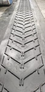
In a limestone quarry or a sand and gravel line, troughing brackets run beneath an abrasion resistant conveyor belt that carries sharp rock, so impact brackets at the crusher discharge are common. In a coal-fired power plant, flame retardant and anti-static belt grades are paired with sturdy carbon steel brackets along the coal conveying route. Cement plants, steel sintering lines, and port ship loaders use similar frames, often with a heavy-duty conveyor belt where tonnage is high.
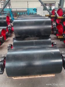
The bracket also works with accessories such as a skirted conveyor belt at loading zones or a corrugated sidewall belt on steep inclines, where roller support must match the belt profile. In every case the conveyor pulley, idler roller, and bracket form one support system, and alignment between them matters more than any single component.
Buyer Checklist Before Ordering
- Confirm belt width, trough angle, and roller diameter as a set.
- Ask for the mounting hole pattern and beam length on the drawing.
- Specify fixed or adjustable brackets for each position.
- State the finish required for dusty, wet, or outdoor service.
- Check that impact and transition positions are identified separately.
Correctly specified conveyor bracket assemblies reduce roller wear and belt mistracking. Buyers should also review the conveyor idler and conveyor roller dimensions against the frame before approving fabrication, since a small mismatch at the bracket can shorten the life of the whole conveyor line.