What an Impact Idler Bracket Does
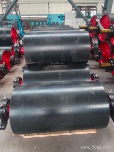
An impact idler bracket is the support structure that holds impact idler rollers at a conveyor transfer point. It absorbs the force of falling material and keeps the belt line stable where the load first lands. In quarry, iron ore, and aggregate operations, this bracket protects both the idler roller and the conveyor belt from repeated shock loading. The bracket itself is often called an impact roller bracket or shock-absorbing idler frame, but it serves the same purpose: positioning and supporting the impact rollers that cushion the belt.
Construction and Mounting
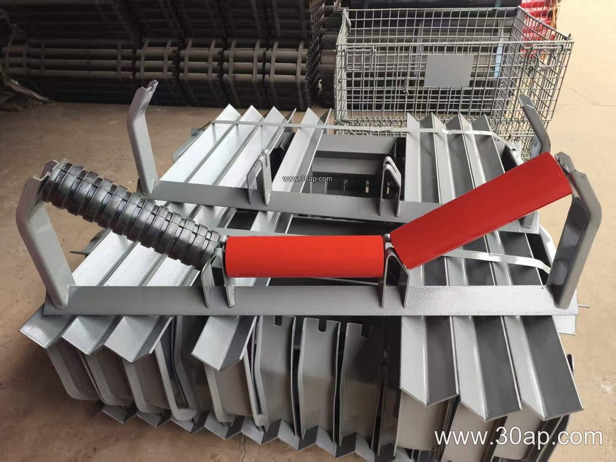
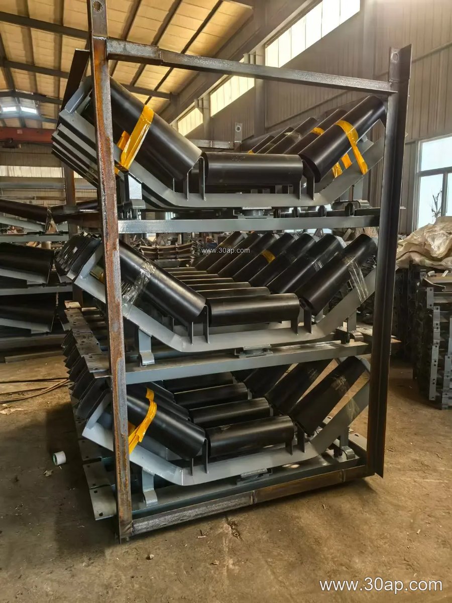
Most impact idler brackets are fabricated from angle steel, channel steel, or folded steel plate. The frame is designed to bolt onto the conveyor stringer or cross beam, and the impact rollers sit in saddle slots or clamped holders. A common arrangement uses a three-roller trough with a 35-degree trough angle for a B1000 conveyor belt, though 30-degree and 45-degree configurations are also used depending on the material and belt width. The bracket may include rubber or spring cushioning elements to further reduce shock. Installation height is set so the impact rollers sit slightly above the normal carrying idlers, allowing the belt to settle onto the standard rollers after the load point.
Where It Fits in the Conveying System
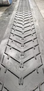
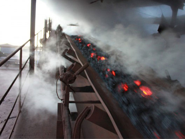
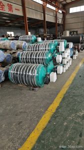
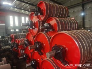
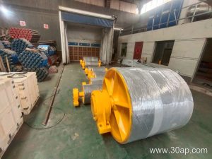
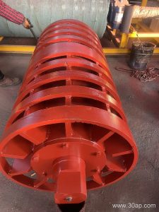
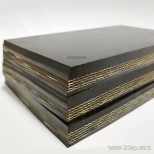
The bracket is installed at the receiving zone, under the chute or crusher discharge. In a coal mining conveyor belt system, the impact idler bracket works alongside the conveyor pulley and conveyor bracket to keep the belt aligned and protected. It is not a substitute for a drive pulley or tail pulley; those components handle power transmission and belt return. The impact bracket is a dedicated load-point support. It is often used with abrasion resistant conveyor belt or impact resistant conveyor belt grades where sharp rock and ore are present.
Common Configurations and Reference Data
Impact idler brackets are selected to match belt width, trough angle, and roller diameter. The table below shows typical combinations, not mandatory pairings. Actual mounting hole spacing and beam length are determined by the conveyor design.
| Belt Width (B) | Typical Trough Angle | Common Roller Diameter | Typical Bracket Material |
|---|---|---|---|
| B650 | 30° | Ø89 | Angle steel |
| B800 | 35° | Ø108 | Channel steel |
| B1000 | 35° | Ø108 or Ø133 | Folded steel plate |
| B1200 | 45° | Ø133 | Channel steel |
| B1400 | 35° or 45° | Ø159 | Folded steel plate |
| B1600 | 45° | Ø159 or Ø194 | Heavy channel steel |
Adjustable versions allow the trough angle to be set between 20 and 45 degrees, which helps when a conveyor handles mixed material sizes. Fixed brackets are simpler and often preferred where the load profile is consistent. For a B1200 conveyor with a 45-degree trough and Ø133 rollers, a heavy-duty fixed bracket is a common choice. A B650 system with 30-degree trough and Ø89 rollers may use a lighter angle-steel frame.
Buyer Checklist
- Confirm belt width and trough angle before ordering; do not assume one belt width matches only one roller diameter.
- Check the mounting hole pattern against the existing conveyor stringer or cross beam.
- Specify the roller diameter and whether the bracket is fixed or adjustable.
- Consider the material drop height and lump size; a higher drop may call for additional cushioning.
- Match the bracket material to the environment—dust, moisture, and corrosion affect steel choice.
- Ensure the bracket is compatible with the idler roller type used at the load point.
For harsh load points, pair the bracket with a heavy-duty mining conveyor belt and quality idler rollers. Related equipment such as the conveyor pulley and conveyor bracket should be reviewed as part of the whole transfer point, not as isolated parts. A well-matched impact idler bracket reduces belt damage and extends roller life in quarry, cement, and power plant coal handling systems.