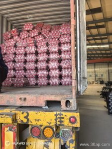
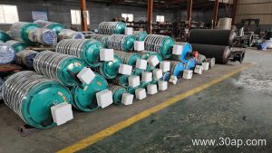
What Conveyor Pulley Welding and Machining Involves
Conveyor pulley welding and machining are the two core fabrication stages that turn steel components into a durable, true-running drum for a belt conveyor. A conveyor pulley is not simply a cylinder with a shaft; it is a pressure vessel of sorts, built to carry the tension of a loaded belt, transmit torque, and resist fatigue over years of service. Whether the pulley is a drive pulley at the head of a quarry conveyor or a tail pulley on a cement plant clinker line, the quality of its welds and the precision of its machining determine how well the belt tracks, how long the lagging lasts, and how often the system needs shutdowns.
Fabrication Sequence from Shell to Finished Pulley
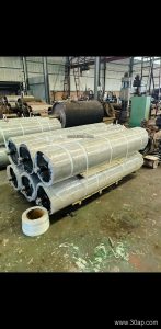
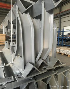
Production typically starts with the shell, which is rolled from steel plate and longitudinally welded. The end discs are then fitted and welded to the shell, followed by the hub and shaft assembly. For a drive pulley, the shaft and hub connection must handle high torque, so welds are often full-penetration and may be inspected by ultrasonic or magnetic particle methods. After welding, the pulley undergoes stress relief or controlled cooling to reduce residual stresses that could cause cracking or distortion.
Machining follows welding. The shaft journals are turned and ground to the required tolerance, the end faces are machined square to the shaft axis, and the shell outside diameter is machined to accept lagging. This stage is critical: an out-of-round shell or a shaft that is not concentric will cause belt tracking problems and vibration. For a bend pulley used in a tensioning position, concentricity matters just as much as it does for the main drive pulley.
Common Pulley Types and Their Welding Focus
Different positions in a conveyor demand different priorities. The table below shows typical pulley types and the fabrication emphasis for each.
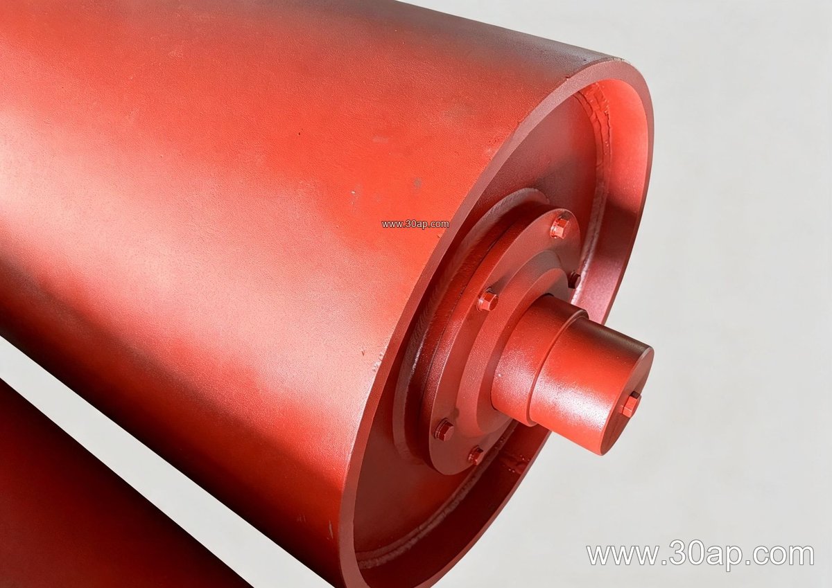
- Drive pulley (head pulley): High torque transfer, full-penetration hub welds, often lagged for grip.
- Tail pulley: Robust shell and end disc welds, resistant to material buildup and belt misalignment.
- Bend pulley: Accurate machining for smooth belt path changes, typically lighter duty than a drive pulley.
- Tension pulley: Strong shaft and hub welds to handle take-up forces.
- Wing pulley: Fabricated from bars rather than a solid shell, used where material buildup is a concern.
Note that drive, tail, and bend pulleys are not interchangeable. A bend pulley cannot simply replace a drive pulley because its weld design, shaft connection, and lagging are chosen for different loads.
Materials and Industries Served
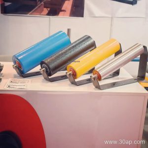
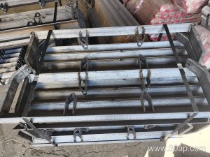
Pulleys are used across bulk handling operations: a limestone quarry feeding a crusher, an iron ore terminal loading ships, a coal washing plant, a power plant coal yard, or a sand and aggregate line. In these environments, the conveyor belt itself—whether a heavy-duty mining conveyor belt, an abrasion resistant conveyor belt, or a flame retardant conveyor belt for underground coal mining—works with the pulley to move material efficiently. The pulley must be matched to the belt’s tension and the idler roller and conveyor bracket arrangement along the line.
Key Parameters for Buyers
When specifying a pulley, several dimensions and features matter. The following table lists common reference values.
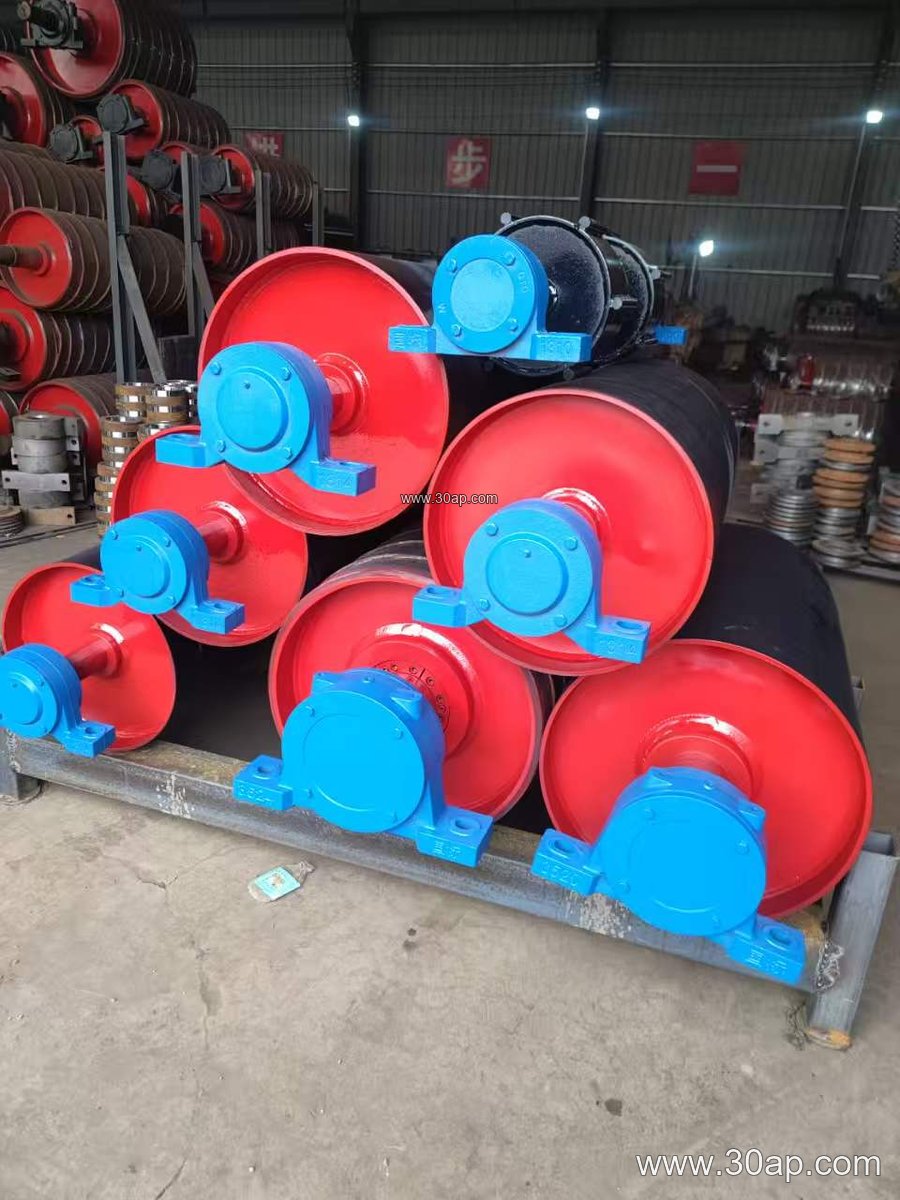
Pulley Dimensions and Surface Options
Belt width (B): B400, B500, B650, B800, B1000, B1200, B1400, B1600, B1800, B2000, B2200, B2400.
Pulley diameter (Ø): Ø200, Ø250, Ø315, Ø320, Ø400, Ø500, Ø630, Ø800, Ø1000, Ø1250, Ø1400, Ø1600, Ø1800.
Shaft diameter: Ø50, Ø60, Ø70, Ø80, Ø90, Ø100, Ø120, Ø140, Ø160, Ø180, Ø200. Shaft size is determined by torque and load, not by belt width alone.
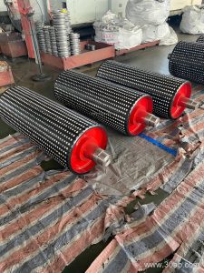
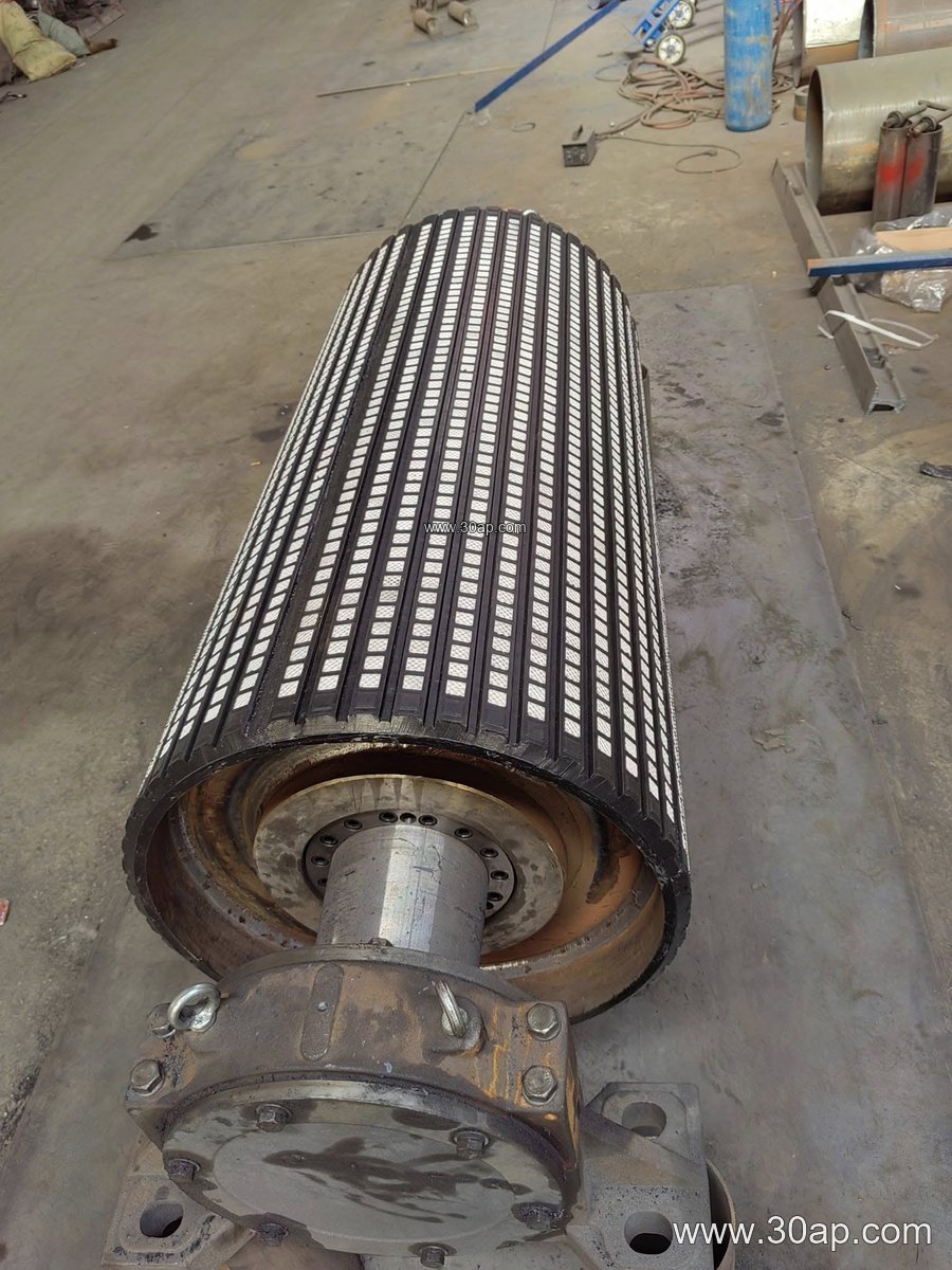
Lagging: plain, molded rubber, cold-bonded rubber, hot-vulcanized rubber, diamond, herringbone, ceramic, or flat rubber. Common lagging thicknesses are 8, 10, 12, 15, and 20 mm.
Shell width is usually wider than the belt; for example, B800 might have a shell around 950 mm, and B1200 around 1400 mm. A combination such as B1200 × Ø1000 or B800 × Ø500 is common, but no single belt width is tied to one diameter—designers select the diameter based on belt tension, wrap angle, and space.
Welding and Machining Quality Checks
Buyers should ask about weld inspection, stress relief, and machining tolerances. A well-made pulley will have documented weld procedures, non-destructive testing where required, and concentricity checks after machining. Balance is another consideration for high-speed pulleys. In a coal mining conveyor belt system, a poorly balanced pulley can accelerate wear on the conveyor belt and idler rollers, leading to unplanned downtime.
Maintenance and Replacement Notes
Even a well-welded and machined pulley needs periodic inspection. Check for cracked welds, worn lagging, shaft wear at the bearing seats, and buildup on the shell. When replacing a pulley, confirm the belt width, pulley diameter, shaft diameter, lagging type, and bearing center distance. Do not assume that a tail pulley can substitute for a bend pulley without checking the load case and weld design. For operators in cement plants, power plants, or port bulk terminals, keeping a spare pulley with the correct specifications can reduce downtime when a failure occurs.
For related conveyor components such as Rubber Conveyor Belt, idler roller, and conveyor bracket, ensure the pulley specification matches the full system design. Proper welding and machining of the conveyor pulley are the foundation of a reliable belt conveyor, whether in a mine, a quarry, or a processing plant.