What Is a Three-Roll Idler Bracket?
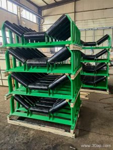
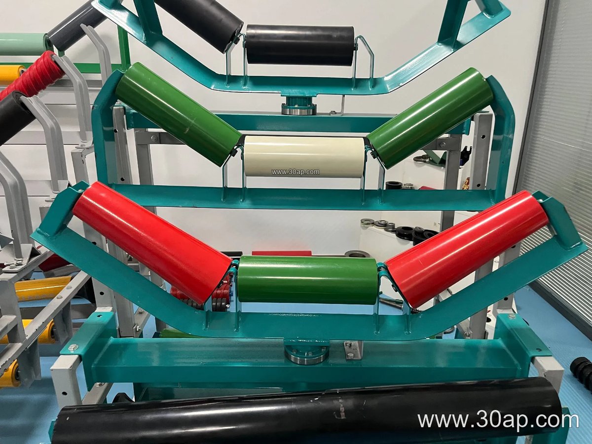
A three-roll idler bracket is the structural support that holds the three idler rollers of a troughing set in a belt conveyor. Often called a troughing idler bracket or three-roller support frame, it keeps the side rollers at a fixed or adjustable trough angle so the conveyor belt forms a stable channel for bulk material. The bracket mounts to the conveyor stringer or cross beam and carries the load from the belt, material, and rollers into the conveyor frame.
In a typical arrangement, the center roller sits horizontal and the two side rollers incline upward. The bracket sets that geometry. This matters in mines, quarries, cement plants, and power station coal yards, where a consistent trough profile helps keep material centered and reduces spillage along the line.
Construction and Common Materials
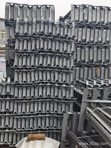
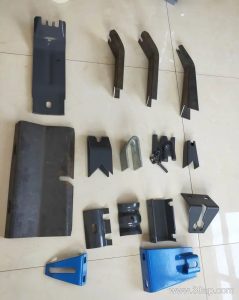
Most brackets are fabricated from angle steel, channel steel, or folded steel plate. The two side supports are angled to match the required trough angle, while the base plate or cross member carries the mounting slots for the idler shafts. Welded or bolted designs both exist. Bolt-on adjustable brackets allow the trough angle to be changed on site, which is useful when a conveyor handles materials with different flow characteristics.
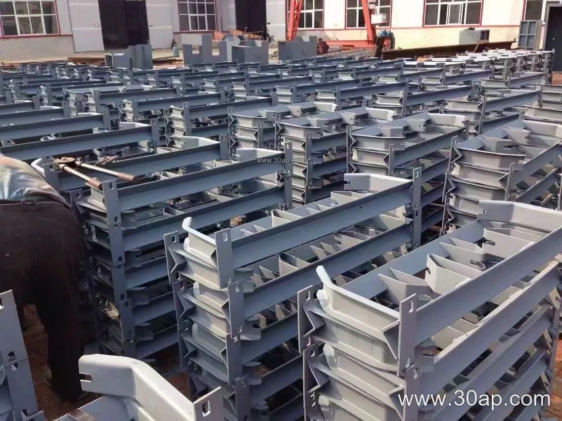
Common trough angles include 20, 30, 35, and 45 degrees. Adjustable versions can move between these angles. Some brackets also incorporate a slight forward tilt of about 1.5 to 2 degrees on the side rollers to help with belt training. The bracket itself is usually matched to the idler roller diameter and the belt width, not chosen in isolation.
Matching Belt Width, Roller Diameter, and Trough Angle
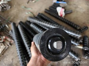
A three-roll idler bracket must fit the conveyor belt width and the roller diameter used on that line. Typical belt widths range from B500 to B2200, and common roller diameters include Ø89, Ø108, Ø133, Ø159, and Ø194. These are reference values, not fixed rules. A B800 conveyor might run 35-degree troughing with Ø108 rollers, while a B1200 line could use 45-degree troughing with Ø133 rollers. The bracket mounting hole spacing and cross beam length are determined by the specific belt width and trough angle.
| Reference Belt Width | Possible Trough Angle | Common Roller Diameter |
|---|---|---|
| B500 | 20° / 30° / 35° | Ø89 |
| B650 | 30° / 35° | Ø89 / Ø108 |
| B800 | 35° / 45° | Ø108 |
| B1000 | 35° / 45° | Ø108 / Ø133 |
| B1200 | 35° / 45° | Ø133 |
| B1400 | 35° / 45° | Ø133 / Ø159 |
| B1600 | 35° / 45° | Ø159 |
| B1800–B2200 | 35° / 45° | Ø159 / Ø194 |
Always confirm the actual bracket drawing against the conveyor design. Do not assume that one belt width only matches one trough angle or one roller diameter.
Where Three-Roll Idler Brackets Are Used
These brackets appear wherever a belt conveyor carries bulk material. In a limestone quarry or crushing and screening line, they support the load zone and the main carrying run. In a cement plant, they guide clinker and raw meal along the belt. In a power plant coal yard, they help keep the conveyor belt centered on long transfer runs. They are also found in iron ore handling, sand and gravel plants, and port loading systems.
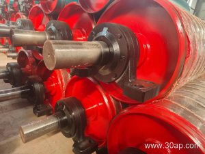
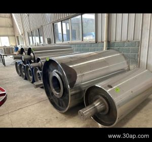
In each case, the bracket works together with the idler rollers and the belt. It is not a substitute for a conveyor pulley at the drive or tail end; pulleys and brackets serve different functions along the conveyor.
Buyer Checklist
- Confirm belt width and required trough angle before ordering.
- Match the bracket to the roller diameter and shaft end type used on the line.
- Decide between fixed and adjustable brackets based on whether the trough angle may need changes.
- Check mounting hole spacing and cross beam length against the conveyor stringer.
- Consider the material being carried and the environment, since abrasive or wet conditions may affect bracket wear and roller choice.
- Ask for a dimensional drawing rather than relying on a generic size table.
A well-matched three-roll idler bracket keeps the trough profile stable, supports the idler rollers properly, and helps the belt run true. For any specific project, the final dimensions should come from the conveyor design, not from a single standard size.