What a Guide Idler Bracket Does
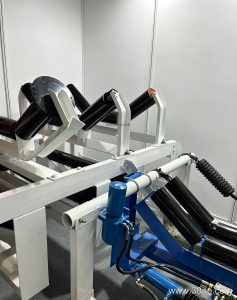
A guide idler bracket is the mounting component that holds a guide, or training, idler in position against the conveyor belt. Its job is not to carry the full material load like a standard carrying idler station. Instead, it keeps the belt tracking near the center line, especially on long runs, inclined sections, and transfer points where the belt tends to wander. In a quarry, a coal washing plant, or a cement clinker line, a small tracking error can lead to edge damage, spillage, and premature wear on the conveyor belt, so this bracket is a small part with a large effect on uptime.
The same component is also called a training idler bracket or self-aligning idler bracket. These are accurate equivalent names for the same product, and they appear interchangeably in conveyor maintenance documents.
How the Bracket Is Built
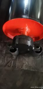
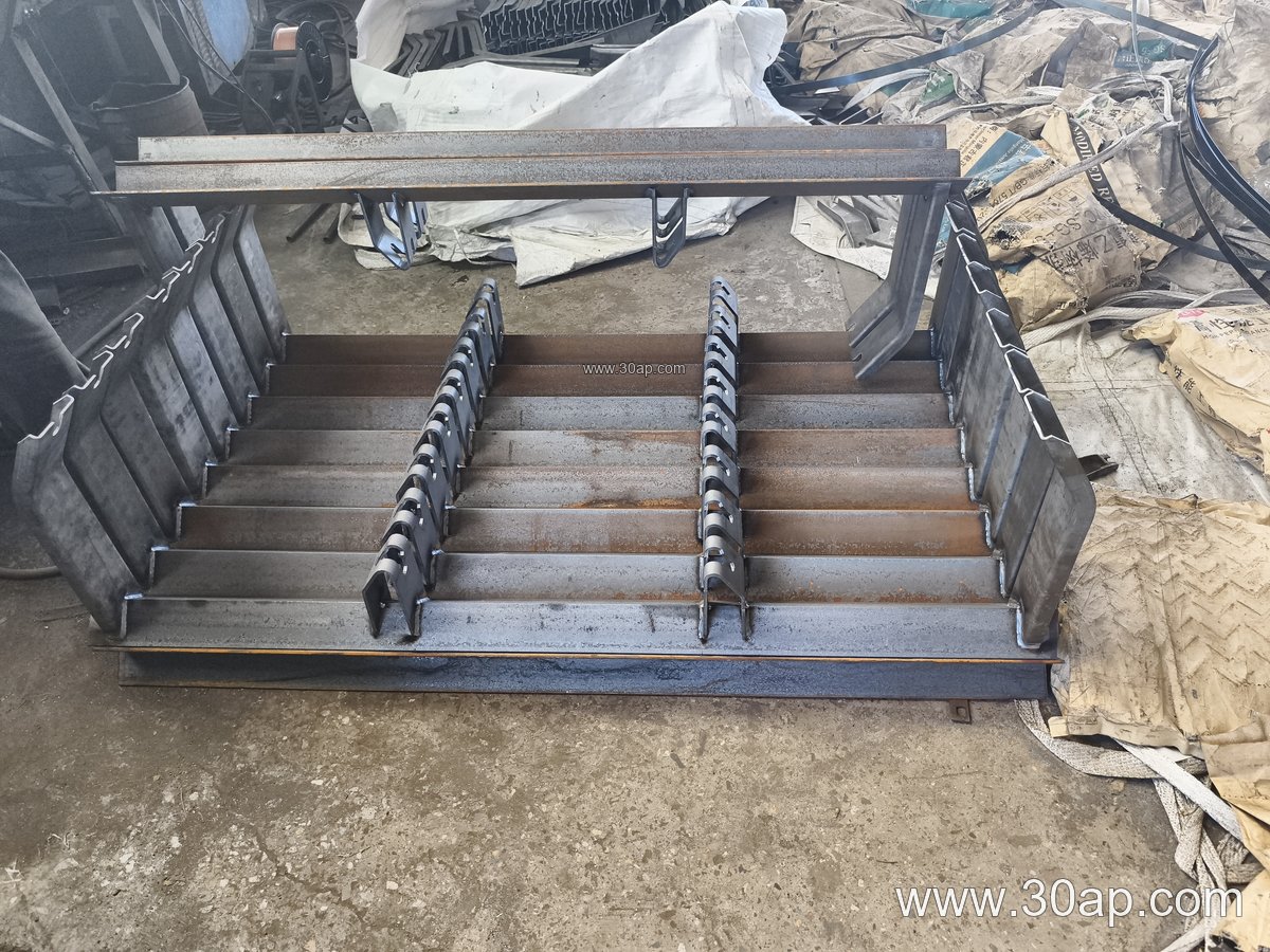
Most units are fabricated from angle steel, channel steel, or folded steel plate, then drilled or slotted for mounting. A typical guide idler bracket assembly includes a base plate, a vertical support, a pivot or swivel point for the self-aligning action, and a mounting face for the idler shaft. On adjustable designs, the bracket also carries slotted holes or a set of position holes so the guide roller can be set at the required angle.
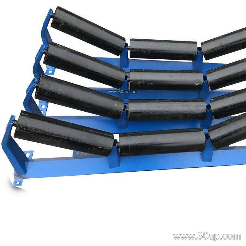
Because the bracket works close to the belt edge, builders usually pay attention to rounded corners, smooth welds, and adequate clearance so the belt and the idler roller do not rub on sharp edges. A well-made bracket keeps the guide roller square to the belt path and allows the roller to rotate freely without binding.
Where It Fits on the Conveyor
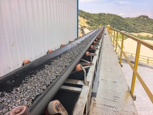
Guide idler brackets are commonly mounted on the carrying side, just ahead of or behind a transfer chute, and on the return side where the belt has a tendency to run off. They are also used on curved sections, inclined conveyors, and shuttle or reversing belts. In a sand and gravel line or a power plant coal handling system, a pair of guide brackets is often installed symmetrically on both sides of the frame.
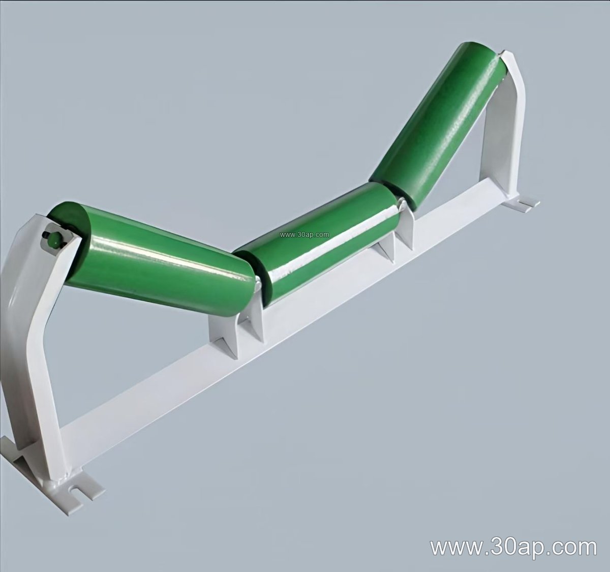
The bracket should be aligned with the conveyor center line and fixed to a rigid part of the frame. A weak or flexible mounting point defeats the purpose, because the bracket itself will move before it can correct the belt.
Common Configurations and Reference Dimensions
The table below shows typical ranges used in conveyor design work. These are reference values, not fixed combinations. Actual mounting hole spacing and crossbeam length depend on belt width, trough angle, and frame design, and should be confirmed against the conveyor drawing.
| Item | Common Options | Notes |
|---|---|---|
| Belt width (B) | B500, B650, B800, B1000, B1200, B1400, B1600, B1800, B2000, B2200 | Bracket size usually follows the frame width |
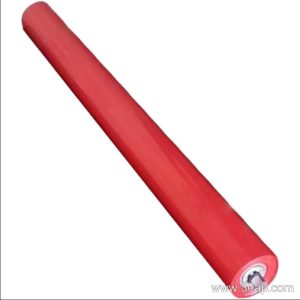
| Guide roller diameter | Ø89, Ø108, Ø133, Ø159, Ø194 | Matched to belt speed and load, not to belt width alone |
| Mounting style | Fixed, adjustable, pivoting | Adjustable versions allow on-site correction |
| Fabrication material | Angle steel, channel steel, folded plate | Coating or galvanizing depends on the environment |
For example, a B800 frame might use a Ø108 guide roller, while a B1200 line may use Ø133. Neither pairing is mandatory. A slow, light-duty conveyor and a heavy, high-speed one can share a belt width but need different roller diameters and bracket stiffness.
Fixed or Adjustable
A fixed guide idler bracket holds the roller at a set angle and is simple and rigid. An adjustable bracket lets maintenance staff change the contact angle or the lateral position after the belt has been run and observed. For a new installation or a conveyor that changes duty, the adjustable type is often easier to commission. For a stable, well-behaved line, the fixed version reduces the chance of settings drifting.
The bracket should not be confused with a troughing idler bracket, which sets the trough angle of the carrying idlers, or with a return bracket that supports the belt on the return strand. Those are different components with different mounting geometry.
Buyer Checklist
- Confirm belt width and frame hole pattern before ordering.
- State the guide roller diameter and shaft end type.
- Choose fixed or adjustable mounting based on how much tuning the line needs.
- Check material and surface treatment for dusty, wet, or corrosive sites such as a coal preparation plant or a fertilizer warehouse.
- Verify clearance to the conveyor belt edge and to nearby structure.
- Ask for the bracket drawing, not just a size code, so the mounting holes match the existing conveyor bracket.
Mounted correctly, a guide idler bracket keeps the belt centered, protects the belt edges, and reduces spillage. It is a modest item in the bill of materials, but one worth specifying with the same care as the conveyor pulley and the idler roller it works beside.