What the Head Drive Pulley Does on a Conveyor
The head drive pulley is the powered drum at the discharge end of a belt conveyor. It transfers torque from the gearbox or motor to the conveyor belt through friction between the drum surface and the belt’s carrying side. Because it sits at the head station, it also sets the belt path as material leaves the conveyor, so its diameter, face width and lagging all influence both traction and belt training. In a quarry or a cement clinker line, this single component often determines how much starting torque the drive can deliver before the belt slips.
It is not the same as a tail pulley, which turns freely at the loading end, nor a bend pulley, which only changes belt direction. Those parts serve different duties and are not interchangeable with the drive drum.
How the Drum Is Built
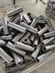
A typical head drive pulley consists of a cylindrical shell, two end discs, a shaft, and hub connections. The shell is usually rolled from steel plate and machined or ground on the outer face so the lagging sits evenly. The shaft is keyed or shrink-fitted to the hubs and carries the bearings in the conveyor bracket assemblies on either side of the frame.
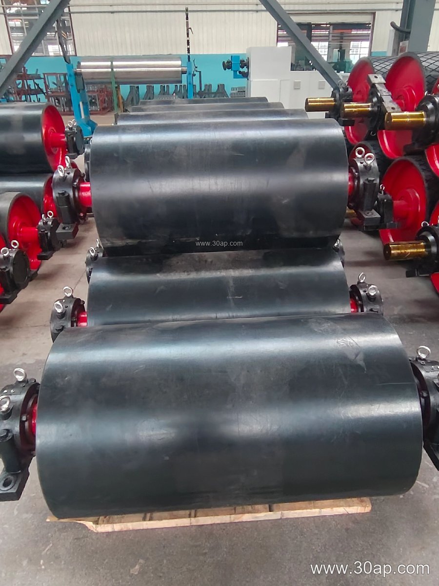
Drive torque is transmitted either through a keyed shaft connection or through a shrink disc, depending on the design. Larger units used in iron ore or copper concentrator conveyors often use a reinforced shell and double-ended shaft so the drive can be mounted on one or both sides.
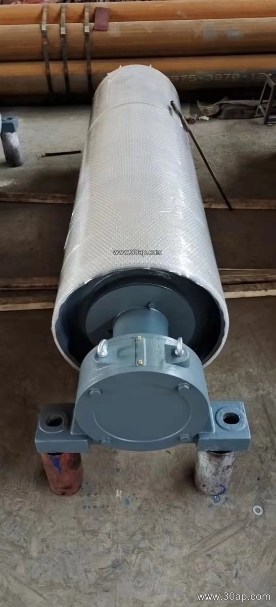
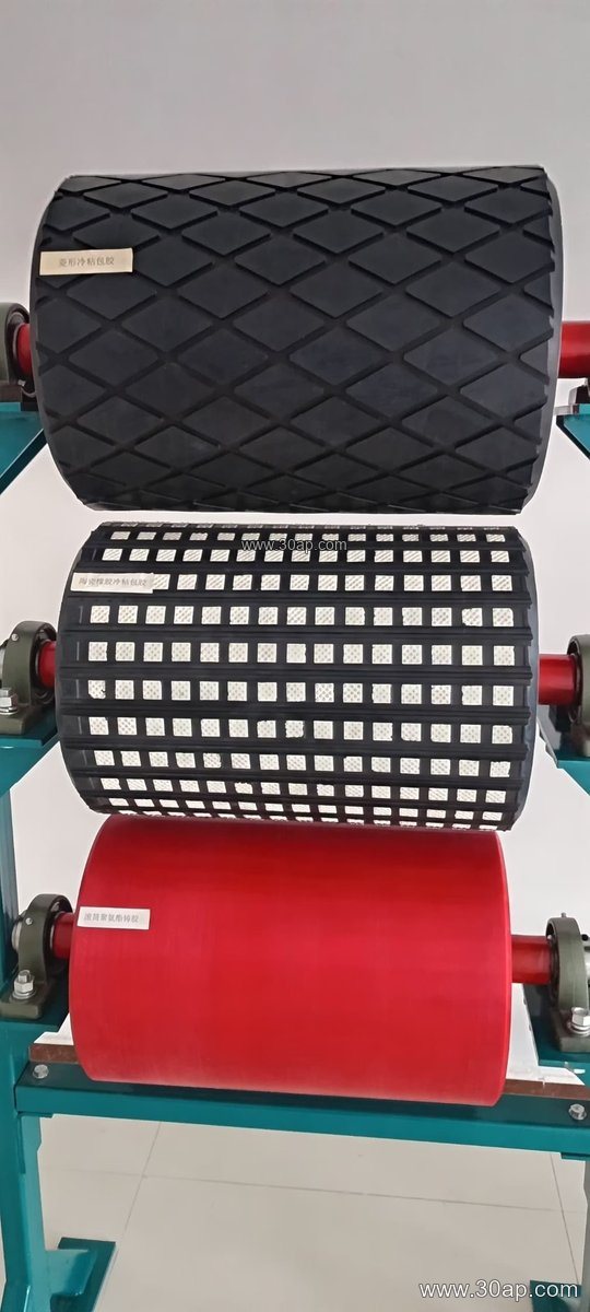
Surface condition matters as much as the shell. Common finishes include:
- Plain steel face for light duty or where belt slip is not a concern
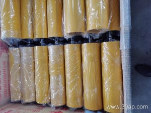
- Hot vulcanized rubber lagging for general bulk handling
- Cold bonded rubber for field replacement
- Diamond or herringbone grooved lagging to improve water shedding and traction
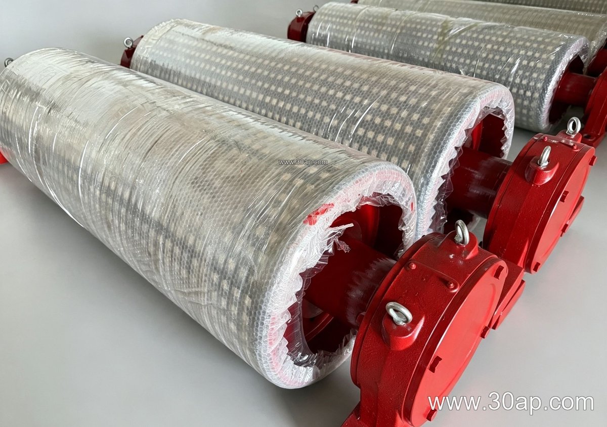
- Ceramic lagging for abrasive service such as sinter or limestone
Lagging thickness commonly falls in the 8, 10, 12, 15 and 20 mm range, chosen according to belt tension and abrasion rather than a fixed rule.
Matching Diameter and Face Width to the Belt
Diameter is not chosen from belt width alone. It depends on the required wrap angle, belt tension, allowable surface pressure on the belt carcass, and the speed of the conveyor. A B800 belt might run on a Ø500 drum in one plant and a Ø630 or Ø800 drum in another where tension and belt stiffness demand it. Similarly, a B1200 system could use Ø1000 or a larger diameter depending on the drive layout.
Face width is normally a little wider than the belt. Reference values often quoted in design work are shown below; these are typical proportions, not fixed supply commitments.
| Belt width | Typical pulley face width | Example diameter range |
|---|---|---|
| B400 | about 500 mm | Ø200 to Ø400 |
| B500 | about 600 mm | Ø250 to Ø500 |
| B650 | about 750 mm | Ø315 to Ø630 |
| B800 | about 950 mm | Ø400 to Ø800 |
| B1000 | about 1150 mm | Ø500 to Ø1000 |
| B1200 | about 1400 mm | Ø630 to Ø1250 |
| B1400 | about 1600 mm | Ø800 to Ø1400 |
| B1600 | about 1800 mm | Ø1000 to Ø1600 |
| B1800 | about 2000 mm | Ø1250 to Ø1800 |
Shaft diameter is determined by torque and bearing load. Common shaft sizes include Ø50, Ø60, Ø70, Ø80, Ø90, Ø100, Ø120, Ø140, Ø160, Ø180 and Ø200, but the correct value comes from the drive calculation, not from the belt width.
Where It Fits in the Plant
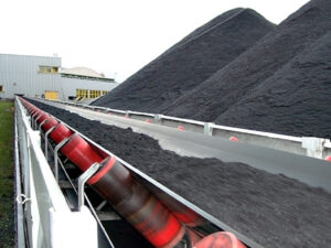
Head drive pulleys appear wherever a belt conveyor discharges material: at the transfer tower of a coal handling system in a power plant, at the top of a crushing and screening circuit in an aggregate quarry, or at the loading point of a port bulk terminal. In a grain silo or fertilizer plant, a smaller drum with smooth lagging may be preferred to avoid product buildup. In tunnel muck removal and concrete batching plants, compact drive drums are often paired with a close-coupled gearbox.
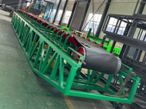
The surrounding hardware matters too. The conveyor belt must be supported by idler rollers along the carrying run, the pulley must sit square in its conveyor bracket, and the take-up arrangement must keep enough tension for the drive to grip. A correctly sized drive drum cannot compensate for a badly aligned frame.
Points a Buyer Should Confirm
Before ordering, clarify the belt width and speed, the calculated torque and belt tension, the required lagging type and thickness, the shaft and bearing arrangement, and whether the drum is to be supplied bare or with a drive coupling. Ask for the surface runout and balancing grade if the conveyor runs at higher speed. Confirm the discharge chute and belt cleaner positions, because they affect how much of the drum face is actually in contact with the belt.
Finally, keep spare lagging and fasteners on hand. A glazed or worn rubber face reduces friction and encourages slip, and in a continuous process such as a washing plant or a sinter line, that slip quickly becomes a downtime issue.