What a Tail Drive Pulley Does
A tail drive pulley is a conveyor pulley mounted at the tail end of a belt conveyor that also serves as a drive point. In most conveying layouts the head pulley does the driving, but some installations place the drive at the tail, either to suit the plant layout or to share traction between two driven pulleys. The tail drive pulley therefore has two jobs: it turns the returning belt and it transmits torque into the conveyor belt through friction between the pulley surface and the belt cover.
It is not the same component as a bend pulley or a plain tail pulley. A bend pulley only changes belt direction, and a non-driven tail pulley only supports and redirects the belt. Because the tail drive pulley carries drive torque, its shaft, bearing housings, locking arrangement and lagging are usually built more heavily than a comparable idler pulley.
How the Pulley Is Built
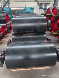
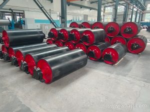
The core is normally a steel shell welded to end discs, with a shaft running through the centre and supported by bearing housings on both sides. The shell is machined so the lagging sits evenly and the belt tracks without wandering. Drive torque reaches the shell through a keyed or shrink-fitted connection to the shaft, and the shaft is coupled to a gearbox and motor, or in some designs to an electric drum motor.
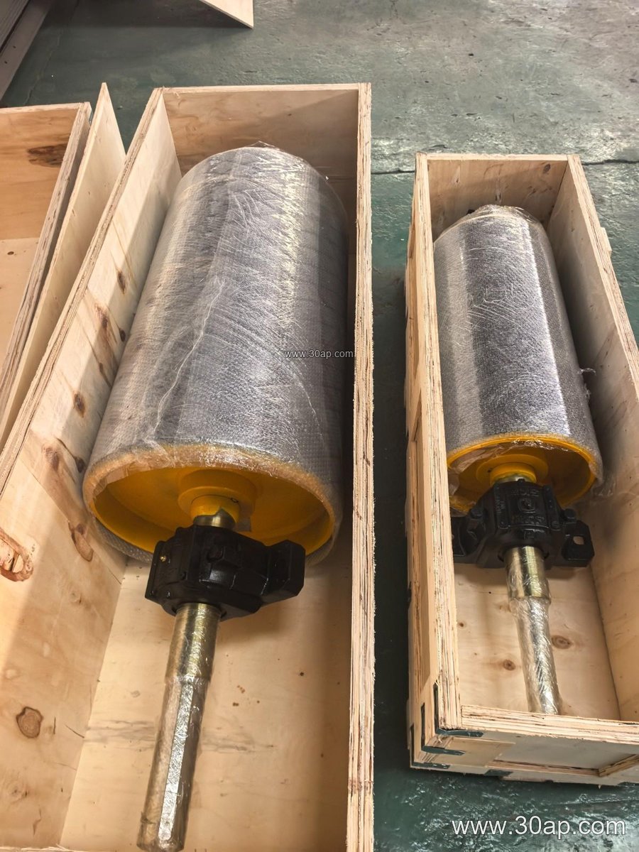
Surface treatment is where the tail drive pulley earns its grip. Common options include plain machined surface, cast rubber, cold-bonded rubber, hot-vulcanised rubber, diamond groove lagging, herringbone lagging and ceramic lagging. Rubber thickness is often 8, 10, 12, 15 or 20 mm depending on belt tension and abrasiveness of the material. In a coal preparation plant or a limestone quarry, diamond or herringbone lagging helps shed fines and water; in a power plant coal handling line, plain or lightly grooved rubber may be enough.
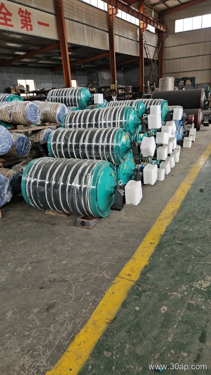
- Shell: rolled and welded steel, machined after welding
- Shaft: forged or turned steel, sized by torque and radial load
- Bearings: spherical roller type in split housings, greased or oil lubricated
- Lagging: rubber, ceramic or plain surface, bonded or vulcanised
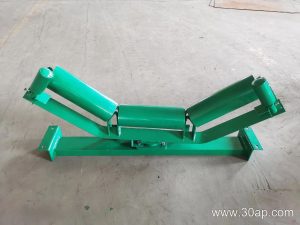
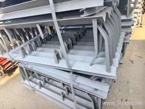
- Accessories: conveyor bracket, scraper mount, speed sensor ring
Where It Fits in the Plant
Tail drives appear in crushing and screening plants where the head end is crowded, in tunnel spoil conveyors where the drive must sit away from the discharge, and in some aggregate stockyard lines. They also suit mobile or semi-mobile conveyors in a sand and gravel pit, where a compact tail-mounted drive keeps the discharge zone clear. In each case the pulley still works with the same surrounding equipment: the conveyor belt, the carrying and return idlers, the conveyor pulley set at the head, and the conveyor bracket that ties the assembly to the frame.
Because the drive is at the tail, belt tension on the return side matters more than in a head-driven layout. A take-up or tension pulley is often placed nearby so the belt wraps the tail drive pulley with enough arc of contact. If wrap is short, a snub or pressure pulley can be added to increase the contact angle.
Sizes and Selection Points
Diameter and face width are chosen from belt width, belt speed, torque and the required wrap angle. The table below shows common reference combinations; they are examples, not fixed pairings.
| Belt width | Typical pulley face width | Example diameter |
|---|---|---|
| B500 | about 600 mm | Ø315, Ø400 |
| B650 | about 750 mm | Ø400, Ø500 |
| B800 | about 950 mm | Ø500, Ø630 |
| B1000 | about 1150 mm | Ø630, Ø800 |
| B1200 | about 1400 mm | Ø800, Ø1000 |
| B1400 | about 1600 mm | Ø1000, Ø1250 |
| B1600 | about 1800 mm | Ø1250, Ø1400 |
Shaft diameter is not derived from belt width alone. Common shaft sizes run from Ø50 up to Ø200, but the correct value comes from torque, belt pull and bearing span. A B800 x Ø500 tail drive pulley and a B1200 x Ø1000 unit may both be reasonable, yet their shafts and bearing sizes will differ according to the drive duty.
Buyers should confirm the belt width, pulley face width, shell diameter, shaft diameter, lagging type and thickness, bearing type, and the coupling or motor arrangement. It also helps to state the material being conveyed, whether the site is a cement plant clinker line, an iron ore transfer point or a fertiliser store, and whether washdown or dusty conditions apply.
Maintenance Notes
Check lagging wear at each shutdown, especially on the driven face where slip first appears. Keep the belt cleaner working so fines do not pack between belt and pulley. Grease bearings to the schedule, watch for shell cracking near the end discs, and verify that the conveyor bracket bolts remain tight. A tail drive pulley that runs true and grips well protects the belt and keeps the whole conveyor pulley train running smoothly.