What an Impact Idler Bracket Does
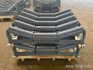
An impact idler bracket is the support frame that holds the impact idler rollers directly beneath a conveyor loading point. It absorbs the force of falling material so the conveyor belt does not take the full blow. In a quarry, a coal preparation plant or a cement plant, the loading chute drops rock, clinker or aggregate onto the belt, and that concentrated impact is exactly what this bracket is built to handle. The bracket is a distinct component from a standard troughing idler bracket, and it is not a substitute for a conveyor pulley or a bend pulley at the head or tail of the system.
Construction and Mounting Position
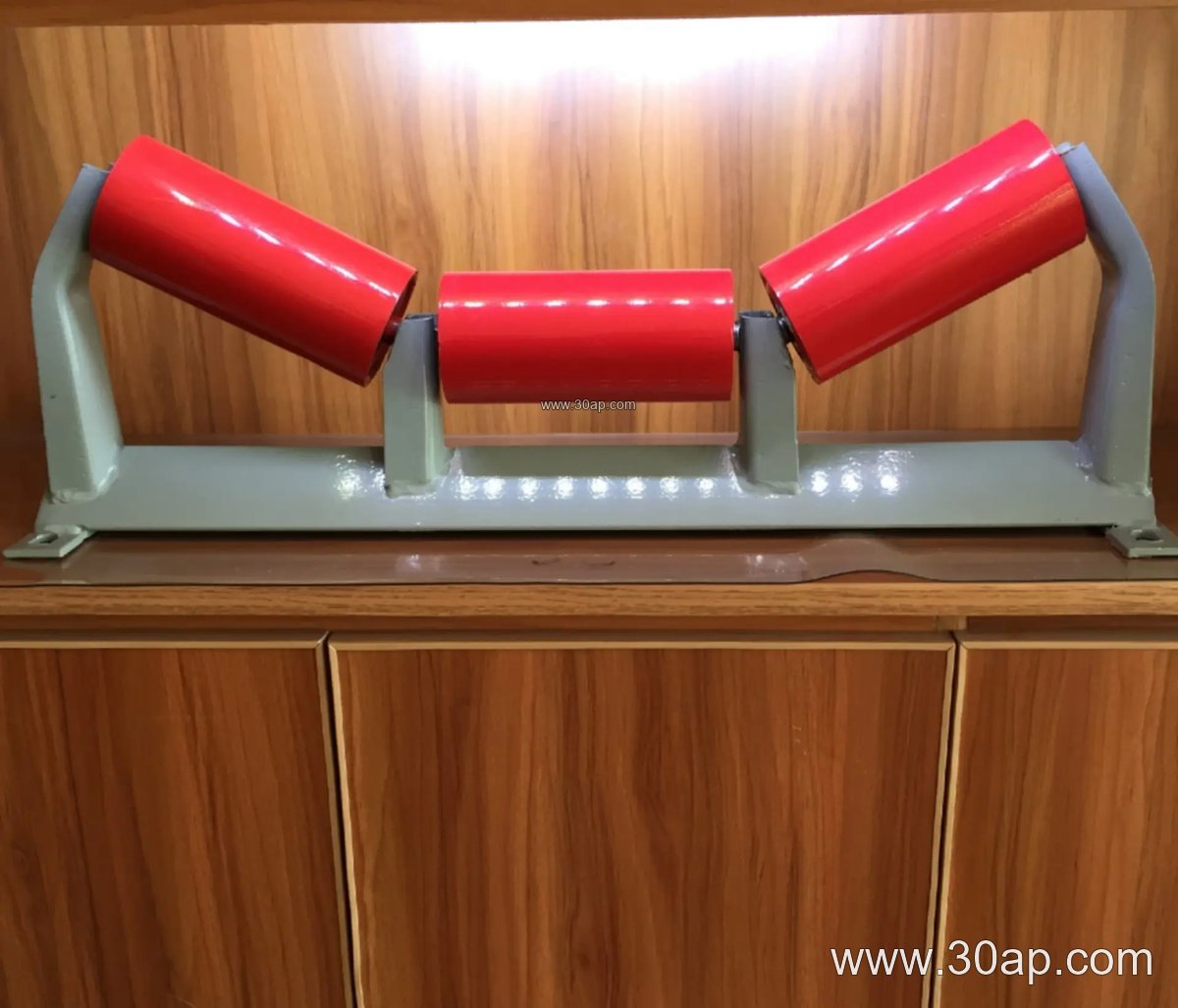
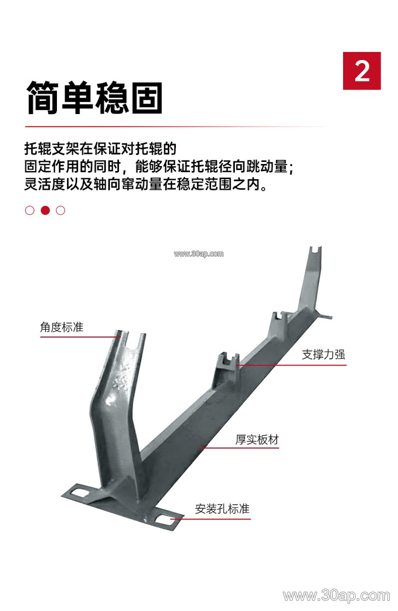
Most impact idler brackets are fabricated from angle steel, channel steel or folded steel plate. The frame is stiffened because it must resist repeated shock rather than steady running load. The bracket mounts to the conveyor stringer or frame at the load zone, and it usually carries a set of impact idler rollers with rubber or other resilient rings. The trough angle is normally fixed at the plant design value, commonly 20, 30, 35 or 45 degrees. The bracket is positioned so the belt sits slightly above the ordinary carrying idlers, giving the belt room to deflect under impact without striking the frame.
Where It Is Used
Impact idler brackets are common in crushing and screening lines, limestone and iron ore mines, coal handling systems and power plant coal yards. They also appear at transfer points in sand and gravel plants and at tunnel spoil handling conveyors. The common factor is a drop point where material velocity is high. Downstream of that point, the belt returns to normal troughing idlers or, on the return strand, to a return bracket or V-return bracket. Alignment along the run may be handled by a self-aligning bracket, but that is a different function and does not replace the impact frame.
Typical Reference Dimensions
The table below gives common reference values for matching an impact idler bracket to a belt and roller set. These are reference figures for discussion, not universal specifications; actual mounting hole spacing and crossbeam length follow the belt width and trough angle, and should be confirmed with the conveyor design.
| Belt width | Typical trough angle | Common roller diameter | Bracket material |
|---|---|---|---|
| B500 | 20 to 30 degrees | Ø89 | Angle steel |
| B650 | 30 degrees | Ø89 to Ø108 | Angle steel or channel |
| B800 | 30 to 35 degrees | Ø108 | Channel steel |
| B1000 | 35 degrees | Ø108 to Ø133 | Folded steel plate |
| B1200 | 35 to 45 degrees | Ø133 | Channel steel |
| B1400 | 35 to 45 degrees | Ø133 to Ø159 | Folded steel plate |
| B1600 | 35 to 45 degrees | Ø159 | Channel or folded plate |
| B1800 to B2200 | 35 to 45 degrees | Ø159 to Ø194 | Heavy channel or folded plate |
Belt width does not lock the bracket to a single trough angle or roller diameter; a B1200 conveyor might run 35 degrees with Ø133 rollers or 45 degrees with the same diameter, depending on the material and belt speed.
What a Buyer Should Check
- Match the bracket trough angle to the existing carrying idler frames so the belt line stays continuous.
- Confirm the roller diameter and the impact roller ring material suit the lump size and drop height.
- Ask for the mounting hole spacing and crossbeam length for the specific belt width, since these vary with design.
- Check that the frame height places the belt slightly above the normal idler line at the load point.
- Consider an adjustable bracket only if the trough angle may be changed later; fixed brackets are simpler at a given angle.
- Inspect the bracket together with the conveyor belt, idler roller and conveyor bracket fixings during scheduled maintenance, since loose bolts at the load zone accelerate wear.
A well-chosen impact idler bracket protects both the belt cover and the idler set beneath the chute. The right frame, roller size and trough angle together keep the loading zone stable in demanding service.