What the head pulley assembly does
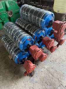
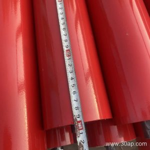
A head pulley assembly is the drive and discharge unit mounted at the delivery end of a belt conveyor. It grips the conveyor belt, pulls the loaded strand forward, and throws material off as the belt wraps around the drum. In many plants the same assembly is simply called the head drum assembly or the drive pulley assembly, because the head position, the driving duty, and the unloading function usually sit in one place. That combination is what separates it from a tail pulley, which mainly redirects the returning belt, and from a bend pulley, which only changes belt direction.
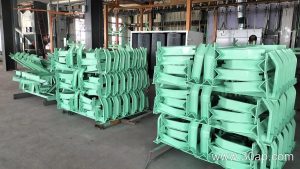
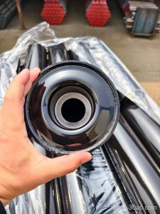
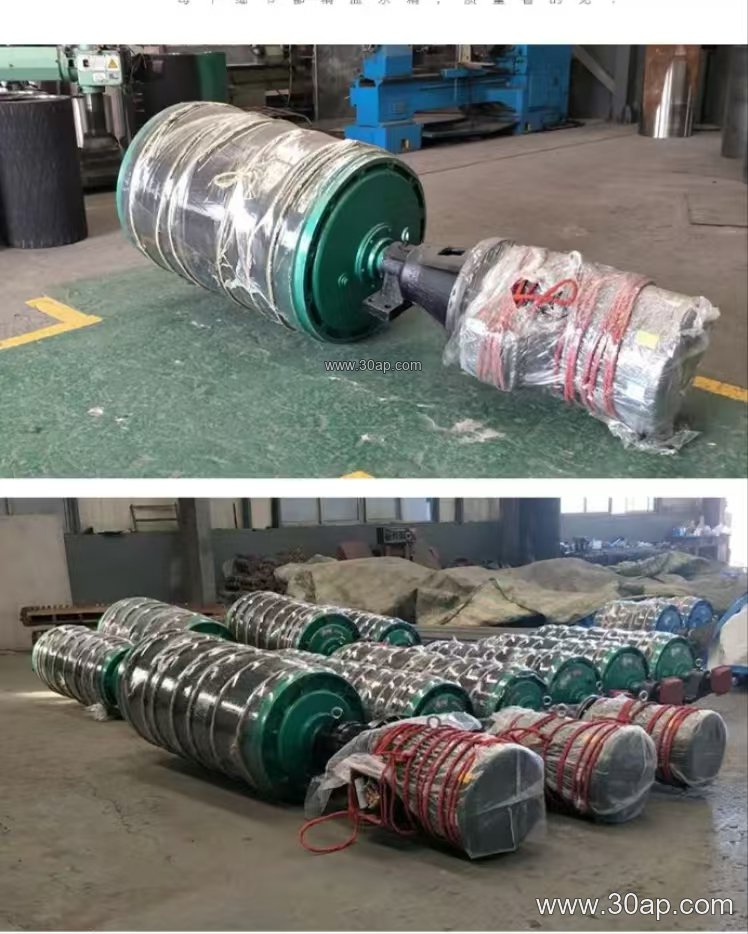
The assembly is more than a bare shell. It normally includes the pulley body, the shaft, bearing housings, locking elements, and the conveyor bracket or frame that ties it to the conveyor structure. Lagging, scraper mounts, and coupling guards are often part of the package.
How the unit is built
The core is a cylindrical shell welded to end discs, with a through shaft or stub shafts pressed and keyed into place. Shell thickness, disc profile, and weld quality are chosen for the belt tension and the torque the drive has to transmit. Bearing selection follows the radial load and the overhung load from the drive arrangement.
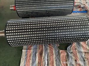
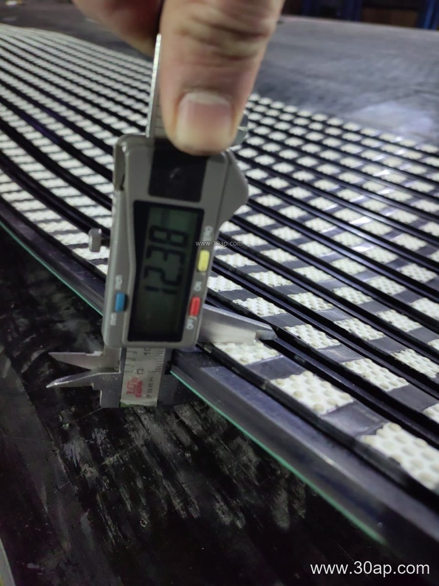
Surface treatment matters at the discharge point. Plain finish is used where grip demand is low and material is dry. Rubber lagging, applied by cold bonding or hot vulcanizing, raises friction and protects the shell. Diamond and herringbone patterns help shed water and fines, while ceramic lagging suits abrasive duty in iron ore, copper ore, or sinter plants. Common lagging thicknesses are 8, 10, 12, 15, and 20 mm.
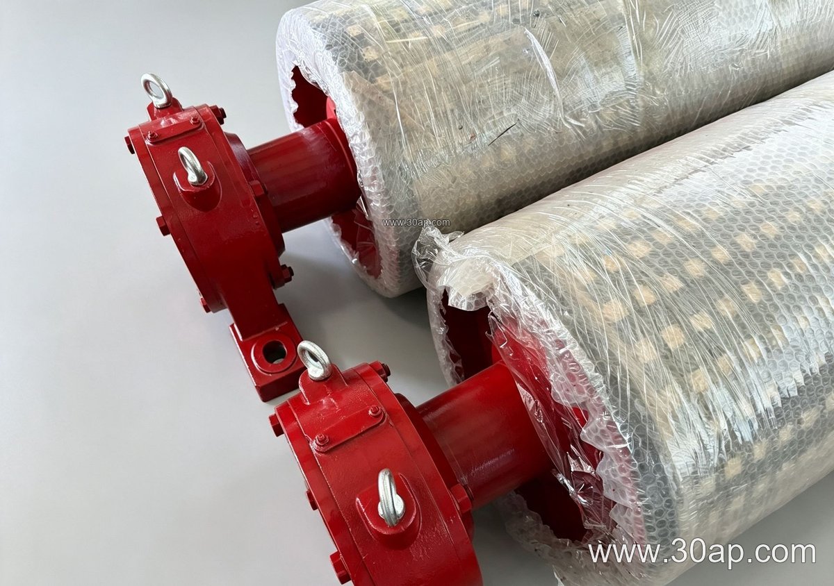
- Shell and end disc welded construction
- Shaft with keyed or shrink-fit connection
- Self-aligning bearing housings on the conveyor bracket
- Lagging in plain, rubber, diamond, herringbone, or ceramic form
- Optional scraper and guard mounting points
Where it is used
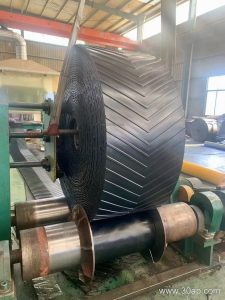
You will find this assembly on the discharge end of nearly every heavy belt conveyor. In a coal washing plant it lifts raw coal from the pit and drops it onto a transfer chute. In a limestone quarry or a crushing and screening line it works alongside the conveyor belt and the conveyor pulley set to move blasted rock toward the primary crusher. Cement plants use it on clinker and raw meal circuits, power stations on coal handling systems, and aggregate yards on stockpile feed lines. Port bulk terminals and tunnel spoil lines rely on the same layout, only with different duty classes.
Sizing notes for buyers
Belt width and drum diameter are related but not locked together. A B800 belt might run on a Ø500 head drum in one plant and a Ø630 drum in another, depending on belt speed, wrap angle, and the amount of torque the drive applies. Typical combinations include B800 × Ø500, B1200 × Ø1000, and B1400 × Ø800, but these are examples, not rules. Diameter should be confirmed against belt construction and the manufacturer’s minimum bend radius.
Face width is usually slightly larger than the belt. Reference values look like this:
| Belt width | Typical face width |
|---|---|
| B400 | about 500 mm |
| B650 | about 750 mm |
| B1000 | about 1150 mm |
| B1400 | about 1600 mm |
| B1800 | about 2000 mm |
Shaft diameter is set by torque and load, not by belt width alone. Common shaft sizes range from Ø50 to Ø200, and a B1000 conveyor may carry a Ø120 shaft in a light duty line or a larger one where the drive is heavy. Never assume a fixed shaft size from the belt number.
Selection and maintenance points
Check the wrap angle first, because it decides how much grip the lagging must provide. Match the lagging pattern to the material: wet fines favor grooved surfaces, while sharp abrasive rock favors ceramic. Confirm that the conveyor bracket height and bolt pattern fit the existing structure, and that the bearing housings allow alignment adjustment. On the maintenance side, watch lagging wear at the discharge edge, re-torque locking elements after the first running period, and keep the scraper clearance correct so carryback does not build up on the return side. A worn head drum shows up as belt slip, tracking drift, and rising motor current, so routine inspection of the shell and lagging pays for itself.