What a Conveyor Pulley Assembly Does
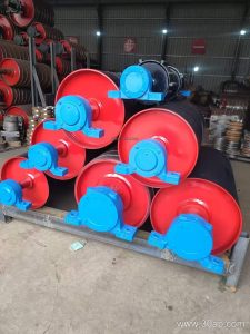
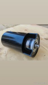
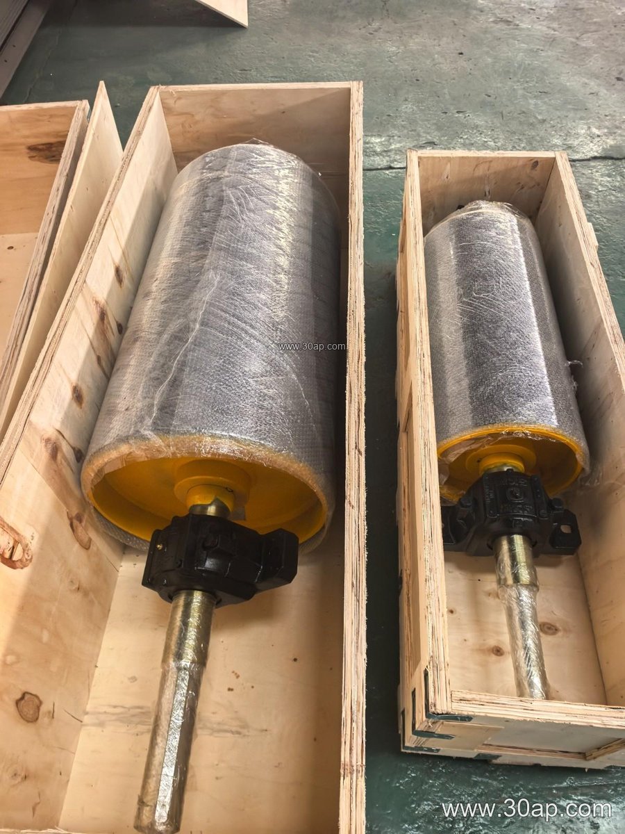
A conveyor pulley assembly is the rotating heart of a belt conveyor. It transmits motion, maintains belt tension, and guides the belt along its path. In a quarry, cement plant, or coal handling system, these assemblies keep material moving reliably. The assembly typically includes the pulley shell, shaft, bearings, bearing housings, and locking elements. The shell may be plain or covered with rubber, ceramic, or other materials to improve grip and wear resistance.
While the term often appears in specifications, it is important to distinguish between functional types. A drive pulley (also called head pulley) powers the belt, a tail pulley redirects it at the loading end, and a bend pulley changes direction along the route. These are not interchangeable names; each has a distinct role in the conveyor layout.
Construction and Key Components
A robust assembly starts with the shell, usually made from rolled steel and machined for balance. The shaft is sized according to torque and load, not simply belt width. Common shaft diameters include Ø50, Ø60, Ø70, Ø80, Ø90, Ø100, Ø120, Ø140, Ø160, Ø180, and Ø200, but the final choice depends on the design. Bearings are selected for radial and axial loads, and housings are sealed to keep out dust and water.
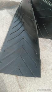
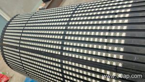
Surface options are critical for performance. Plain (smooth) shells suit lighter duties, while rubber lagging – applied by cold bonding or hot vulcanization – increases friction. Diamond or herringbone patterns improve traction in wet conditions, and ceramic lagging offers exceptional wear resistance in abrasive environments like iron ore or limestone. Lagging thickness commonly ranges from 8 mm to 20 mm, with 10 mm and 12 mm being frequent choices for general service.
Matching Belt Width and Pulley Dimensions
Pulley face width is usually slightly larger than the belt width to ensure full support. For example, a B800 belt typically uses a pulley face around 950 mm, and a B1200 belt around 1400 mm. Diameter selection is driven by belt speed, tension, and the required wrap angle. A B800 conveyor might use a Ø500 drive pulley, while a B1400 system could use a Ø800 or Ø1000 tail pulley. These are common pairings, not fixed rules; each conveyor is engineered individually.
The table below lists typical reference dimensions for common belt widths. Always confirm final sizes with the conveyor designer.
| Belt Width | Typical Pulley Face Width (mm) | Common Diameter Range (mm) |
|---|---|---|
| B400 | 500 | Ø200 – Ø315 |
| B500 | 600 | Ø250 – Ø400 |
| B650 | 750 | Ø315 – Ø500 |
| B800 | 950 | Ø400 – Ø630 |
| B1000 | 1150 | Ø500 – Ø800 |
| B1200 | 1400 | Ø630 – Ø1000 |
| B1400 | 1600 | Ø800 – Ø1250 |
| B1600 | 1800 | Ø1000 – Ø1400 |
| B1800 | 2000 | Ø1250 – Ø1600 |
| B2000 | 2200 | Ø1400 – Ø1800 |
Where These Assemblies Are Used
In a sand and gravel plant, a tail pulley assembly might be fitted with a self-cleaning wing pulley to shed sticky material. In a coal-fired power station, drive pulleys with diamond lagging handle high tension on long overland conveyors. Other industries include copper mines, fertilizer plants, and grain silos. The choice of assembly depends on the material, environment, and conveyor duty.
Buyer Checklist
- Define the pulley function: drive, tail, bend, take-up, or snub. Each has different design priorities.
- Confirm belt width and required face width – usually belt width plus 100–200 mm.
- Specify shaft diameter based on torque and load, not on belt width alone.
- Select lagging type and thickness for the operating conditions: plain, rubber, ceramic, or patterned.
- Check bearing type, sealing, and housing compatibility with the conveyor bracket.
- Consider maintenance access and whether a removable bearing housing is needed.
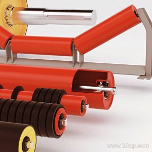
Work with a qualified engineer to match the conveyor pulley assembly to your conveyor belt, idler rollers, and structural brackets. Proper selection ensures reliable service and reduces downtime in demanding industries.