What a Belt Conveyor Idler Frame Does
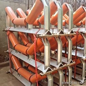
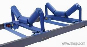
A belt conveyor idler frame is the structural support that holds idler rollers in the correct position along a conveyor. It keeps the conveyor belt at the desired profile, whether that is a troughed carrying run or a flat return run. In a quarry, a cement plant, or a coal handling system, the frame is the interface between the idler roller and the conveyor bracket or stringer. Without a properly built frame, the belt can misalign, the rollers can wear unevenly, and the whole conveyor becomes less efficient.
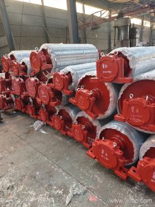
The frame is not a pulley. Drive pulleys, tail pulleys, and bend pulleys have completely different roles. Those components transmit power or change belt direction, while the idler frame simply carries the belt and its load. This article focuses on the idler frame itself, with occasional comparisons where they help clarify the frame’s job.
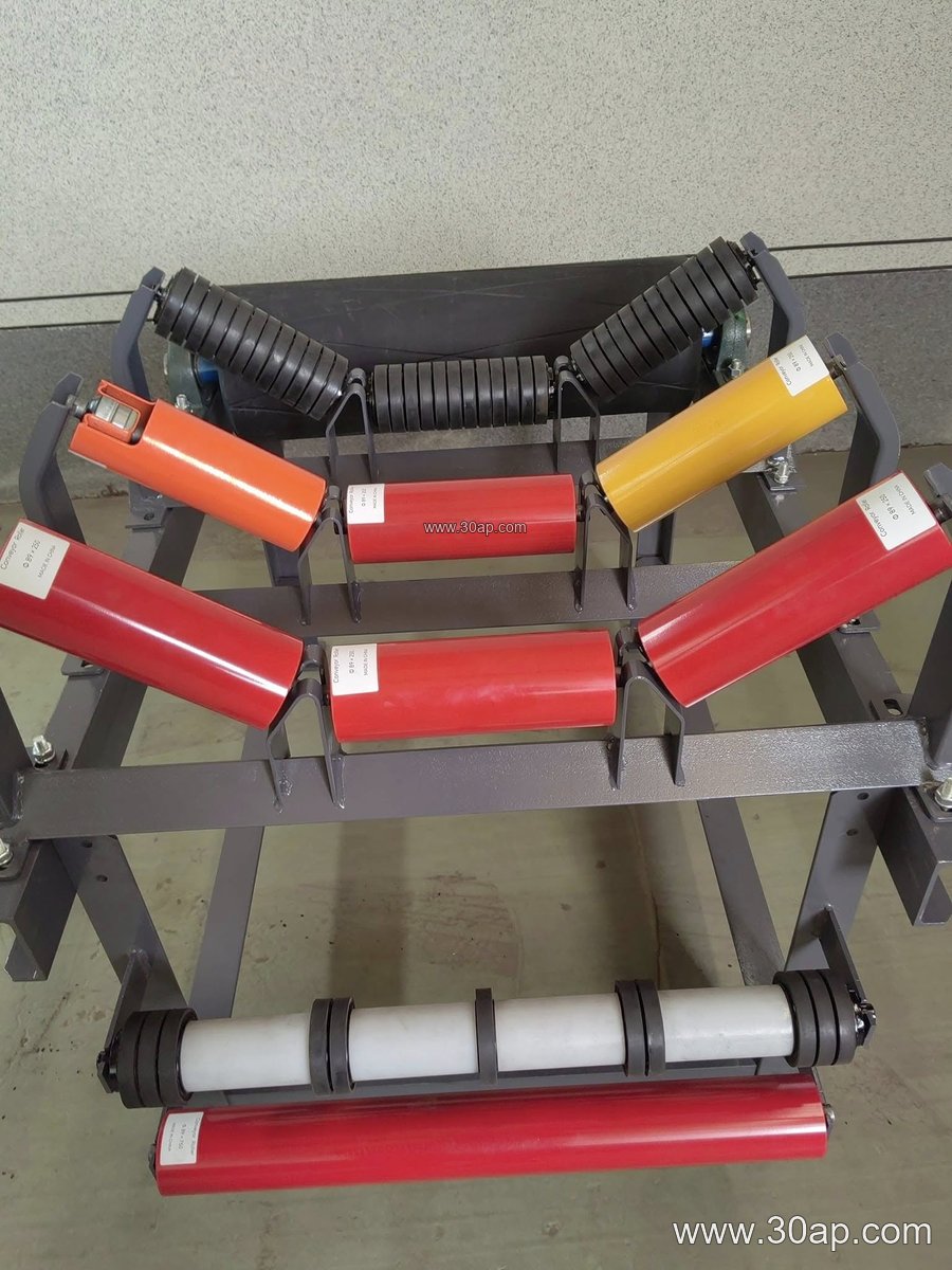
How an Idler Frame Is Built
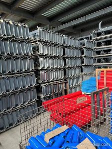
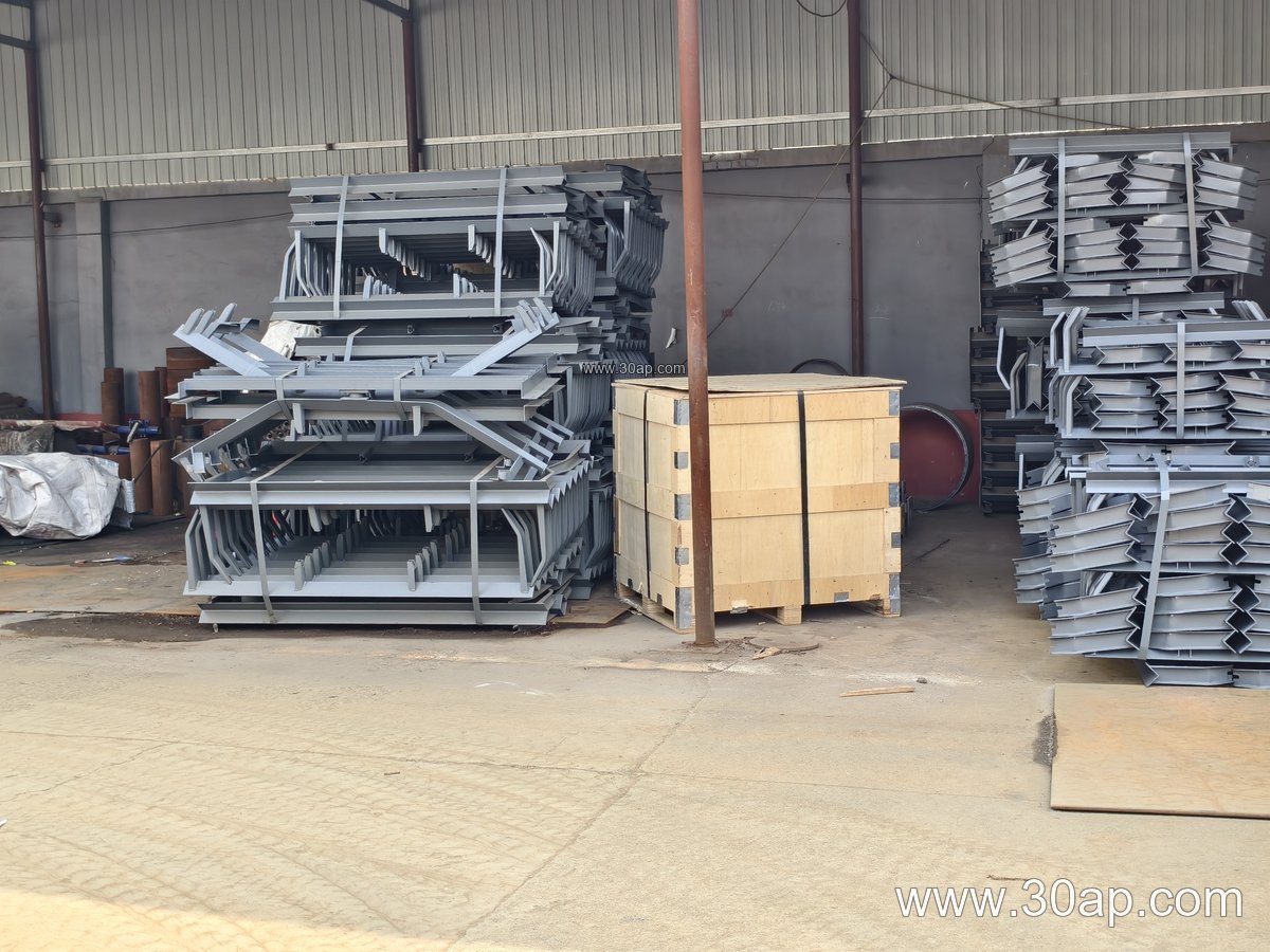
Most frames are fabricated from angle steel, channel steel, or folded steel plate. The choice depends on the load and the environment. A heavy-duty frame for an iron ore mine may use thicker channel sections, while a lighter frame for a sand and gravel line might use folded plate. The frame includes mounting slots or holes for the idler roller shafts, and these are positioned to achieve a specific trough angle.
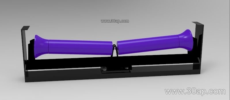
Common trough angles are 20, 30, 35, and 45 degrees. Adjustable frames can be set to different angles within that range, which is useful when a conveyor handles materials with varying characteristics. Forward tilt of about 1.5 to 2 degrees is sometimes built into the frame to help center the belt. The frame length and hole spacing change with belt width and trough angle, so they are not fixed numbers.
Types of Idler Frames and Where They Fit
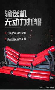
Different positions on a conveyor call for different frame types. The main carrying side usually uses a troughing frame, often called a trough idler frame, with three or more rollers. The return side may use a flat return frame or a V-return frame. Transition frames are placed near pulleys to gradually change the belt from flat to troughed. Impact frames, with cushioning rollers, are used at loading points. Self-aligning frames help correct belt tracking, and suspended frames are used where space is tight.
The table below shows common frame types and their typical applications. These are reference examples, not a mandatory list for every conveyor.
| Frame Type | Typical Position | Common Belt Widths (B) | Common Roller Diameter | Notes |
|---|---|---|---|---|
| Troughing frame (30°) | Carrying run | B500 to B1200 | Ø89, Ø108, Ø133 | Three-roller design, fixed or adjustable |
| Troughing frame (35°) | Carrying run | B650 to B1400 | Ø108, Ø133, Ø159 | Higher angle for larger capacity |
| Troughing frame (45°) | Carrying run | B800 to B1600 | Ø133, Ø159, Ø194 | Deep trough for fine materials |
| Transition frame | Near head or tail pulley | B800 to B1800 | Ø108 to Ø159 | Gradual angle change |
| Impact frame | Loading point | B650 to B1400 | Ø89 to Ø159 | With cushion rollers |
| Flat return frame | Return run | B500 to B2000 | Ø89 to Ø194 | Single or double roller |
| V-return frame | Return run | B800 to B2200 | Ø108 to Ø194 | Two rollers in V shape |
| Self-aligning frame | Carrying or return | B650 to B1800 | Ø89 to Ø159 | Helps belt tracking |
Belt width and roller diameter are matched by design, not by a single rule. A B800 conveyor might use Ø108 rollers with a 35-degree frame in one plant and Ø133 rollers with a 30-degree frame in another. The right combination depends on load, speed, and material lump size. Do not assume that one belt width can only pair with one roller diameter.
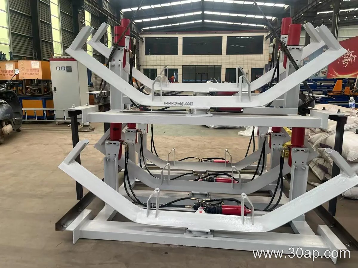
Materials and Construction Details
Frames are usually made of carbon steel and may be painted or galvanized for corrosion resistance. In a fertilizer plant or a grain silo, corrosion protection matters more than in a dry limestone quarry. The frame should be rigid enough to keep the idler rollers aligned. Welds should be clean and free of sharp edges that could damage the conveyor belt. Bolt holes should match the conveyor bracket or stringer spacing.
What Buyers Should Check
- Confirm the belt width (for example B800, B1000, B1200) and the required trough angle.
- Check the roller diameter (Ø89, Ø108, Ø133, Ø159, Ø194) and the frame’s shaft mounting.
- Decide between fixed and adjustable frames. Adjustable frames offer flexibility but may cost more.
- Match the frame material and finish to the environment, such as a coal mine, a power plant coal yard, or a port terminal.
- Verify hole spacing and overall length against the conveyor bracket layout, since these vary with belt width and angle.
- Consider the transition zones near pulleys, where a transition frame helps avoid belt stress.
In a crushing and screening plant, a well-chosen idler frame keeps the conveyor belt running true and extends idler roller life. The same principle applies in a steel mill sinter line or a tunnel muck removal system. The frame is a simple component, but it has a direct effect on conveyor reliability.
Installation and Maintenance Notes
Install the frame squarely to the conveyor centerline. A twisted frame will cause the belt to run off. Check that all fasteners are tight and that the frame sits at the correct height. During maintenance, inspect for bent or corroded frames. A damaged frame can misalign the idler roller and wear the belt edge. Replace frames that no longer hold the correct angle or spacing. Keep spare frames for critical conveyors, especially in continuous operations such as a power plant coal handling system or a cement kiln feed line.