What Is a Head Bend Pulley?
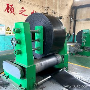
A head bend pulley is a type of conveyor pulley used at the head end of a belt conveyor to redirect the conveyor belt, typically to increase the wrap angle around the drive pulley or to guide the belt into the discharge zone. It is often confused with a drive pulley or a tail pulley, but its primary function is to change the belt path rather than to transmit driving force or to tension the belt. In many conveyor layouts, the head bend pulley works alongside the drive pulley and helps maintain proper belt tracking and tension.
This pulley is also known as a head redirect pulley or head snub pulley. It should not be confused with other pulley types such as the drive pulley, tail pulley, or take-up pulley, each of which has a distinct role in the conveyor system.
Construction and Key Components
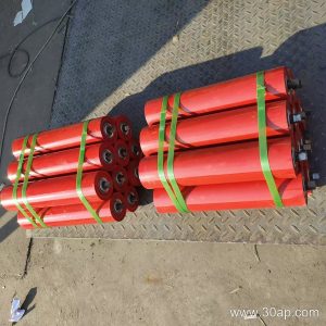
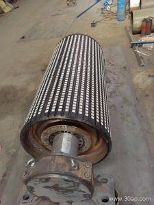
A head bend pulley is built around a cylindrical shell, usually made from steel, with shafts, bearings, and bearing housings. The shell may be machined and balanced to ensure smooth rotation. Surface options include plain finish, rubber lagging, and ceramic lagging, depending on the need for grip or wear resistance. Lagging is often applied to improve friction between the pulley and the conveyor belt, especially in wet or dusty conditions.
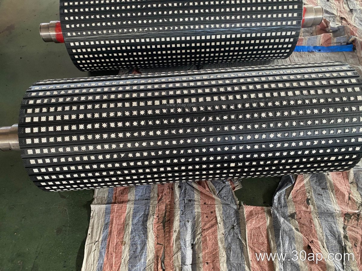
Common surface forms for a head bend pulley include plain, cold-bonded rubber, hot-vulcanized rubber, diamond pattern lagging, and ceramic lagging. Lagging thickness typically ranges from 8 mm to 20 mm, with 10 mm and 12 mm being frequent choices for general applications. The pulley diameter and face width are selected based on belt width, belt tension, and the required wrap angle. For example, a B800 conveyor might use a head bend pulley with a diameter of Ø500 or Ø630, while a B1200 system could employ a Ø800 or Ø1000 pulley. These are typical combinations, not fixed rules.
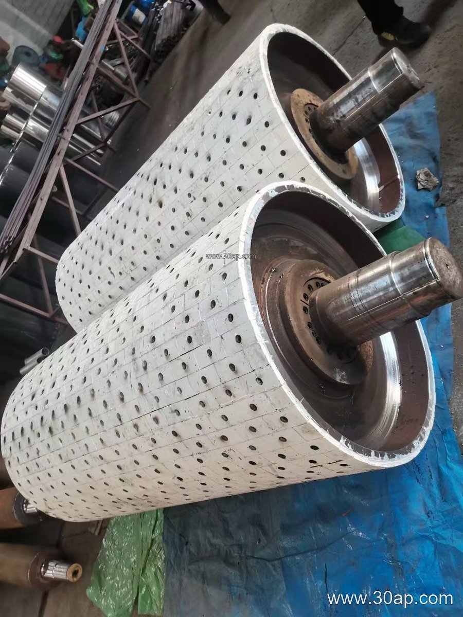
Bearing selection and shaft diameter are determined by the load and torque requirements. Common shaft diameters include Ø80, Ø100, Ø120, and Ø140, but the final size depends on the specific design. The pulley is usually mounted on a conveyor bracket or frame, and proper alignment is critical for reliable operation.
Where It Is Used
Head bend pulleys are found in a wide range of bulk material handling operations. In a limestone quarry, they help route the conveyor belt around the head drive station, ensuring a clean transition to the discharge chute. In a coal washing plant, a head bend pulley with lagging may be used to maintain belt grip in wet conditions. Cement plants, power plant coal handling systems, and aggregate crushing circuits also rely on these pulleys to manage belt paths in tight spaces.
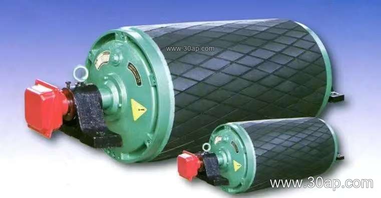
They are particularly useful when the drive pulley needs a larger wrap angle than the natural belt path provides. By adding a head bend pulley, the belt can be redirected to increase contact with the drive pulley, improving traction without relocating the entire drive assembly. In such cases, the head bend pulley works in conjunction with the main drive pulley and the conveyor belt to achieve the desired performance.
Selection and Sizing Considerations
When selecting a head bend pulley, several factors must be evaluated. Belt width is a starting point: common belt widths include B500, B650, B800, B1000, B1200, B1400, and B1600. The pulley face width is usually slightly larger than the belt width; for instance, a B650 belt often pairs with a 750 mm face width, and a B1000 belt with a 1150 mm face width. However, these are general guidelines, and actual dimensions should be confirmed with the pulley manufacturer.
Diameter selection depends on belt tension, desired wrap angle, and space constraints. A larger diameter reduces belt bending stress and can extend belt life. Typical diameters for head bend pulleys range from Ø200 to Ø1400, with Ø315, Ø400, Ø500, and Ø630 being common in medium-duty applications. The shaft diameter is determined by torque and load, not by belt width alone. For example, a B800 conveyor might use a Ø100 shaft, while a B1400 system could require a Ø160 shaft or larger.
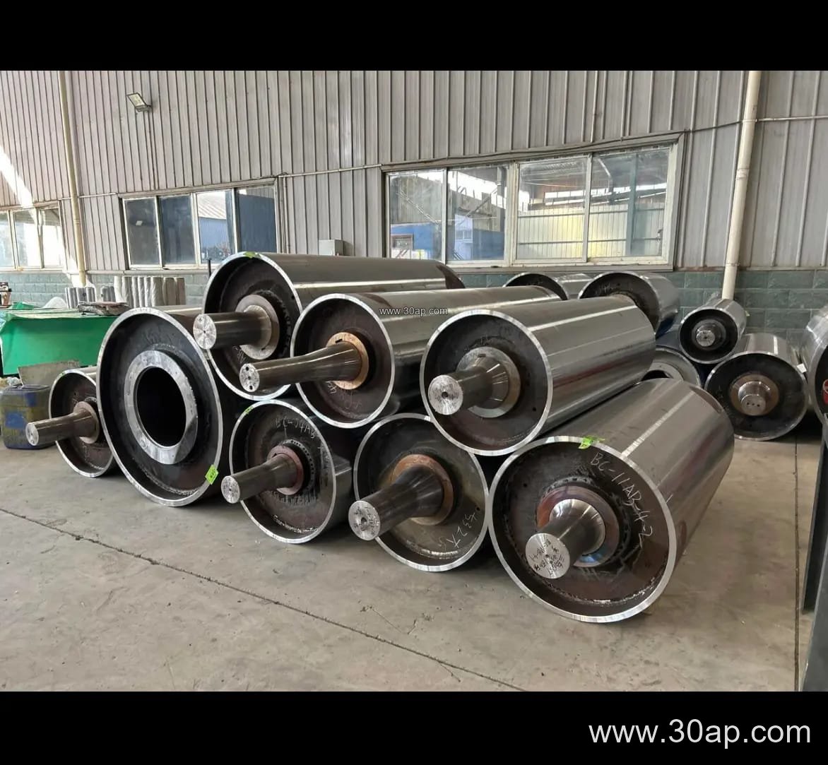
Surface lagging should be chosen based on the environment. Plain steel pulleys are suitable for dry, clean conditions. Rubber lagging (cold-bonded or hot-vulcanized) improves friction and is common in dusty or wet environments. Diamond pattern lagging offers additional grip and is often used in mining and aggregate operations. Ceramic lagging provides high wear resistance for abrasive materials. Lagging thickness of 10 mm or 12 mm is typical, but thicker lagging (15 mm or 20 mm) may be specified for heavy-duty service.
Installation and Maintenance Tips
Proper installation ensures the head bend pulley functions correctly and lasts long. The pulley should be aligned with the conveyor centerline, and the shaft should be level. Misalignment can cause belt tracking issues and premature bearing failure. Regular inspection of the lagging surface is recommended; worn or damaged lagging should be replaced to maintain friction. Bearing lubrication should follow the manufacturer’s schedule, and any abnormal noise or vibration should be investigated promptly.
Keeping the conveyor belt clean and properly tensioned also helps extend pulley life. In dusty environments such as a sand and gravel plant, periodic cleaning of the pulley surface prevents material buildup that could affect belt tracking. When replacing a head bend pulley, verify that the new pulley’s dimensions, lagging type, and shaft size match the original specifications or are approved by the conveyor designer.