What a Steel Plant Conveyor Pulley Does
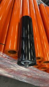
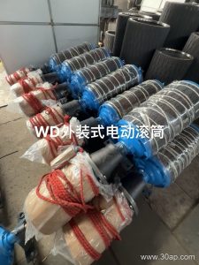
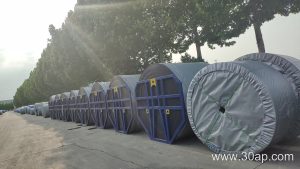
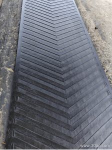
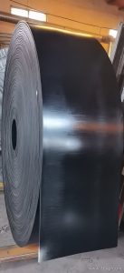
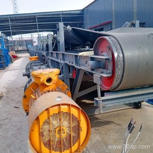
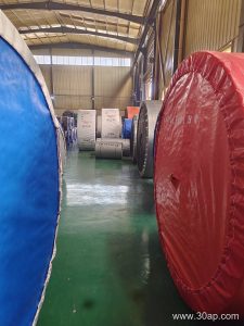
A steel plant conveyor pulley is the rotating drum that drives, tensions, or redirects the conveyor belt in a bulk material handling line. Around a steel mill, you will see these drums on sinter feed lines, coke and coal conveying systems, limestone and additive transport, and slag or scale handling circuits. The pulley is not a standalone item; it works together with the conveyor belt, idler roller sets, and conveyor bracket assemblies to keep a continuous flow of hot or abrasive material moving. The same product is often called a conveyor drum or belt pulley, and that equivalent name refers to the same component.
Drive Pulley and Tail Pulley Are Different Jobs
The drive pulley, sometimes called the head pulley, transmits torque to the belt and is usually the largest and most heavily built drum on the line. The tail pulley sits at the opposite end and mainly supports the belt return. A bend pulley changes belt direction, while a tension pulley takes up slack. These subtypes are not interchangeable: a bend pulley cannot replace a drive pulley, and a tail pulley should not be specified where a drive pulley is needed. Choosing the right role first is more important than choosing a diameter.
How the Drum Is Built
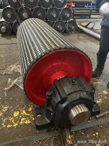
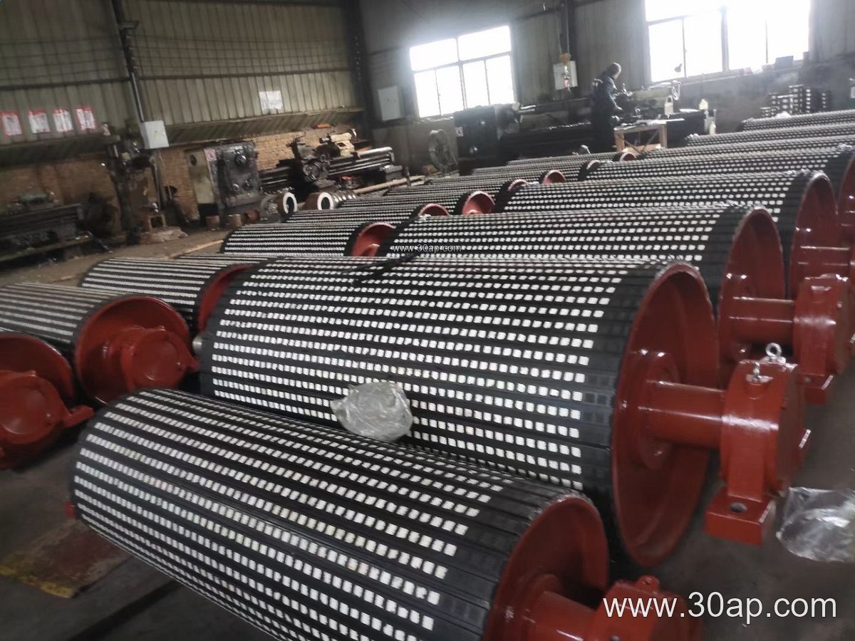
Most steel plant units use a welded steel shell with machined end discs, a through shaft, and bearing housings. The shell may be plain, or it may carry a rubber or ceramic lagging to improve grip.
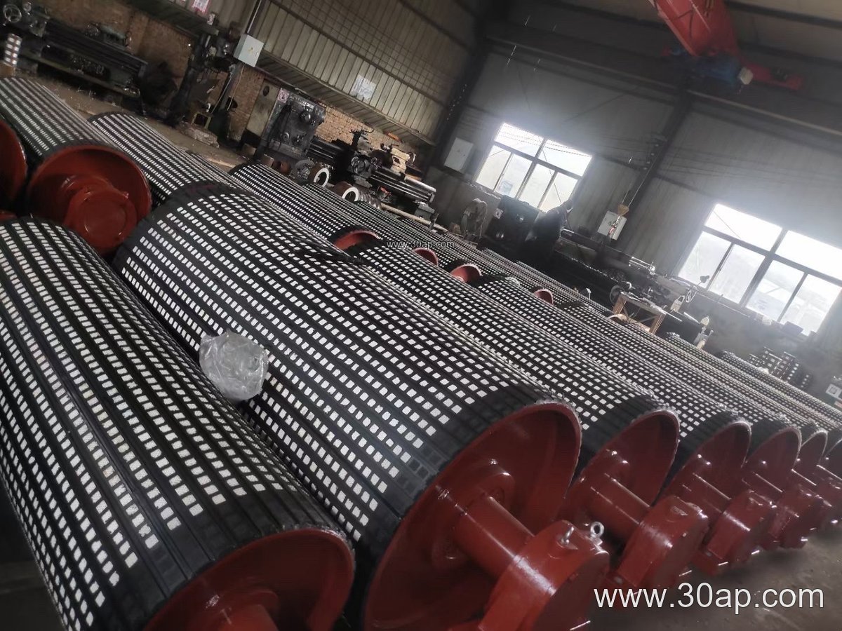
- Shell and end disc welded, then machined for balance
- Shaft sized by torque and radial load, not by belt width alone
- Lagging in plain, cold-bonded rubber, hot-vulcanized rubber, diamond, herringbone, or ceramic form
- Bearing selection matched to load, speed, and dust exposure
Lagging thickness commonly falls in the 8, 10, 12, 15, and 20 mm range. Diamond or herringbone patterns help shed water and fines, while ceramic lagging suits highly abrasive service. For sinter and coke lines, heat resistance of the rubber compound matters as much as the pattern.
Common Reference Dimensions
The table below shows typical reference values, not fixed pairings. A given belt width can work with more than one drum diameter, and the final choice depends on belt tension, wrap angle, and shaft load.
| Belt width | Typical face width | Reference diameters |
|---|---|---|
| B500 | about 600 mm | Ø250, Ø315, Ø400 |
| B650 | about 750 mm | Ø315, Ø400, Ø500 |
| B800 | about 950 mm | Ø400, Ø500, Ø630 |
| B1000 | about 1150 mm | Ø500, Ø630, Ø800 |
| B1200 | about 1400 mm | Ø630, Ø800, Ø1000 |
| B1400 | about 1600 mm | Ø800, Ø1000, Ø1250 |
| B1600 | about 1800 mm | Ø1000, Ø1250, Ø1400 |
Face width is normally a little wider than the belt. Combinations such as B800 × Ø500 or B1200 × Ø1000 are common on paper, but they are design examples rather than rules. Shaft diameters typically run from Ø50 up to Ø200, again set by calculated torque and bearing load.
Where These Drums Are Used
Inside a steel works, the drive pulley usually sits at the discharge end of a sinter or coke line, where it must handle steady load and fine dust. In a coal yard feeding the boiler house, a lagged head drum and a matching tail drum keep the belt tracking. At a limestone or additive crushing station, a bend pulley may be added to increase wrap angle on the drive. Downstream, the same drum family appears in slag handling and in the conveyor that carries mill scale to a collection bin.
What a Buyer Should Check
- Confirm the duty: drive, tail, bend, tension, or snub position
- State belt width, belt speed, and expected tension range
- Specify lagging type and thickness if extra grip or wear protection is needed
- Provide shaft and bearing details, or ask for a load-based recommendation
- Check that the conveyor bracket and bearing housing fit the existing frame
- Plan inspection of lagging wear and bearing condition during scheduled shutdowns
Good communication on these points keeps a steel plant conveyor pulley matched to its line, its belt, and its maintenance window.