What an Iron Ore Conveyor Pulley Does on the Line
An iron ore conveyor pulley is the cylindrical component that turns the conveyor belt, transfers drive torque, and sets belt tension at the head, tail, or intermediate points of a bulk handling conveyor. In a crushing and screening circuit or a sintering plant feed line, this component works under abrasive dust, heavy loads, and constant vibration, so the difference between a standard conveyor pulley and one built for iron ore duty usually comes down to shell thickness, shaft design, bearing selection, and lagging.
The same product is also called a conveyor drum or belt pulley in many workshops. These are equivalent names for the same assembly, not different machine types.
How the Assembly Is Built
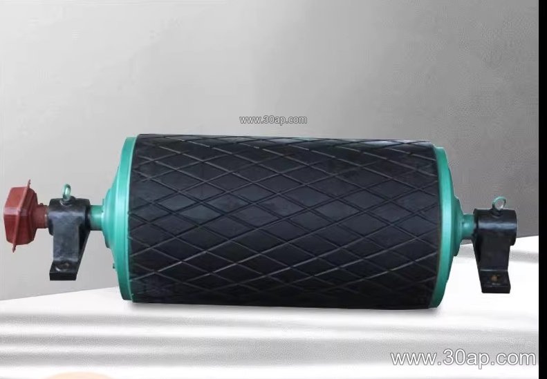
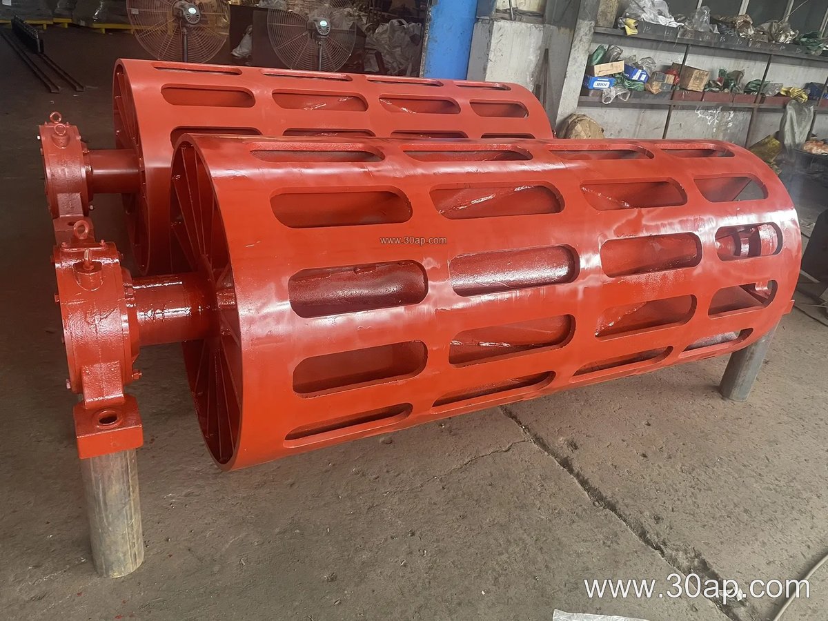
A typical unit consists of a rolled steel shell, two end discs, a through shaft or stub shafts, bearing housings, and a lagging layer. The shell is machined for concentricity, the end discs are welded or bolted, and the shaft is keyed or shrink-fitted to transmit torque. Bearings are usually spherical roller types in pillow block housings, mounted on a conveyor bracket or frame.
Surface treatment matters in iron ore service. Plain steel shells can polish and slip when the belt is wet or dusty, so most iron ore installations use lagging. Common surface forms include:
- Plain (smooth) surface for light duty and low tension
- Diamond grooved rubber lagging for general grip and water shedding
- Herringbone lagging for better self-cleaning on dusty belts
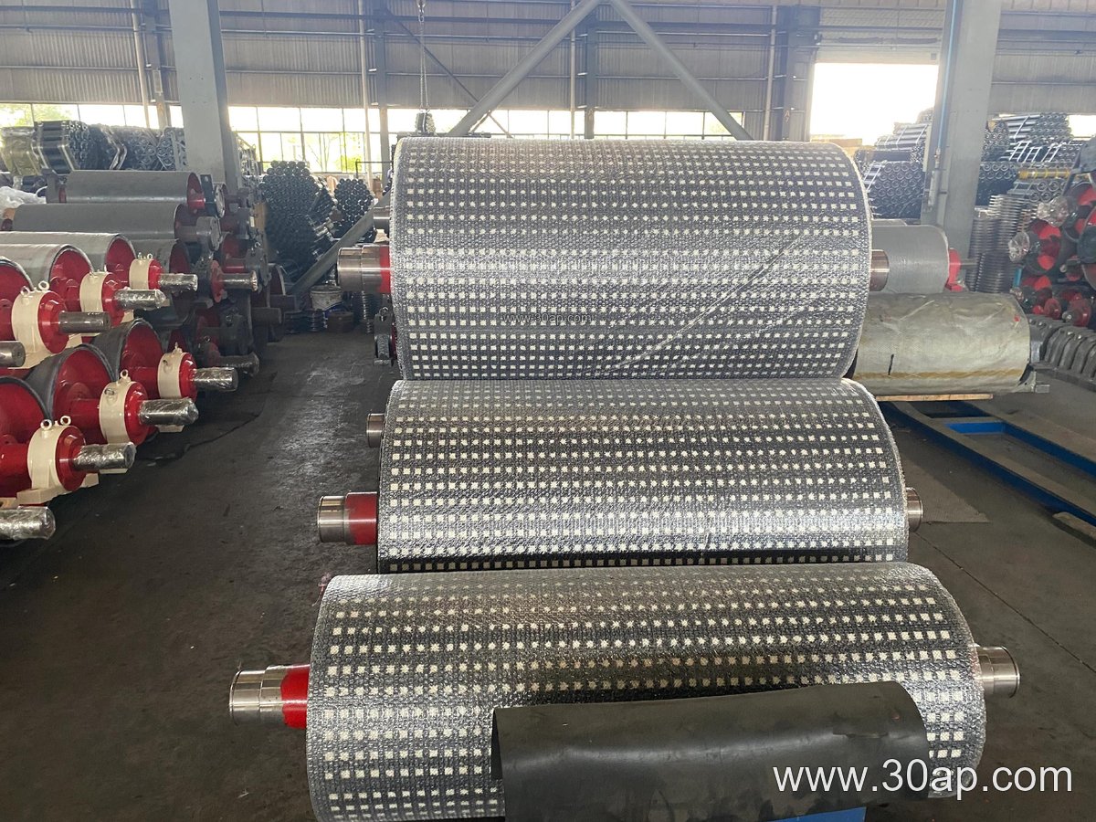
- Ceramic lagging for high-torque drive positions
Lagging thickness commonly falls in the 8, 10, 12, 15, or 20 mm range, selected according to duty and belt speed.
Drive, Tail, and Bend Positions Are Not the Same
The position on the conveyor changes the design. A drive pulley (also called the head or discharge pulley) transmits power from the gearbox and usually carries the heaviest torque, so it often gets thicker lagging, larger shafts, and a reinforced shell. A tail pulley at the loading end mainly guides and tensions the returning belt and may be self-cleaning. A bend pulley changes belt direction without driving; a take-up pulley maintains tension, and a snub or pressure pulley increases wrap angle around the drive.
These are separate roles. A bend pulley should not be specified as a substitute for a drive pulley, and a tail pulley is not interchangeable with a drive pulley even when the diameters look similar.
Common Reference Dimensions
Below are typical reference values, not fixed rules. Final dimensions are set by the conveyor designer based on belt width, tension, torque, and load.
| Belt width | Typical face width | Common pulley diameters |
|---|---|---|
| B500 | about 600 mm | Ø250, Ø315, Ø400 |
| B650 | about 750 mm | Ø315, Ø400, Ø500 |
| B800 | about 950 mm | Ø400, Ø500, Ø630 |
| B1000 | about 1150 mm | Ø500, Ø630, Ø800 |
| B1200 | about 1400 mm | Ø630, Ø800, Ø1000 |
| B1400 | about 1600 mm | Ø800, Ø1000, Ø1250 |
| B1600 | about 1800 mm | Ø1000, Ø1250, Ø1400 |
Shaft diameters commonly range from Ø50 to Ø200 mm, but the correct value depends on torque and bearing load, not on belt width alone. For example, a B1200 × Ø1000 drive pulley and a B800 × Ø500 tail pulley may both appear on the same line, each sized for its own job.
What a Buyer Should Check
Before ordering, confirm the belt width, the pulley position, the required face width, the shaft and bearing arrangement, and the lagging type and thickness. Ask how the shell and end discs are welded, how the shaft is fixed, and whether the lagging is cold-bonded, hot-vulcanized, or cast. In iron ore plants, dust and fines penetrate joints, so sealed bearing housings and good drainage matter.
Also plan maintenance: check lagging wear, belt tracking, and bearing temperature regularly. A worn lagging surface on a drive pulley reduces grip and can cause belt slip, while a misaligned bend pulley can damage the conveyor belt edge. Matching the pulley to the conveyor belt, idler roller set, and frame is part of the same design task, not an afterthought.