What an Anti-Slip Lagged Pulley Does
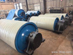
An anti-slip lagged pulley is a conveyor pulley whose cylindrical shell is covered with a rubber or ceramic layer to increase friction between the drum and the conveyor belt. Also called a rubber-lagged drum or lagged head pulley, it is most often found at the drive position, where torque must transfer from the pulley to the belt without slipping. In a quarry, a coal preparation plant, or a cement clinker line, a standard smooth drum can lose grip when the belt is wet, dusty, or heavily loaded. The lagging restores that grip and protects the shell from abrasive wear at the same time.
This article focuses on the anti-slip lagged pulley itself. Drive, tail, and bend pulleys serve different roles and are not interchangeable. A tail pulley, for example, may also be lagged, but its job is to guide and tension the belt rather than transmit drive torque.
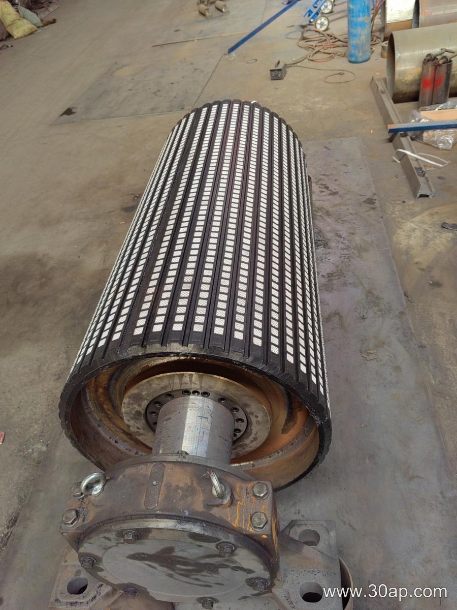
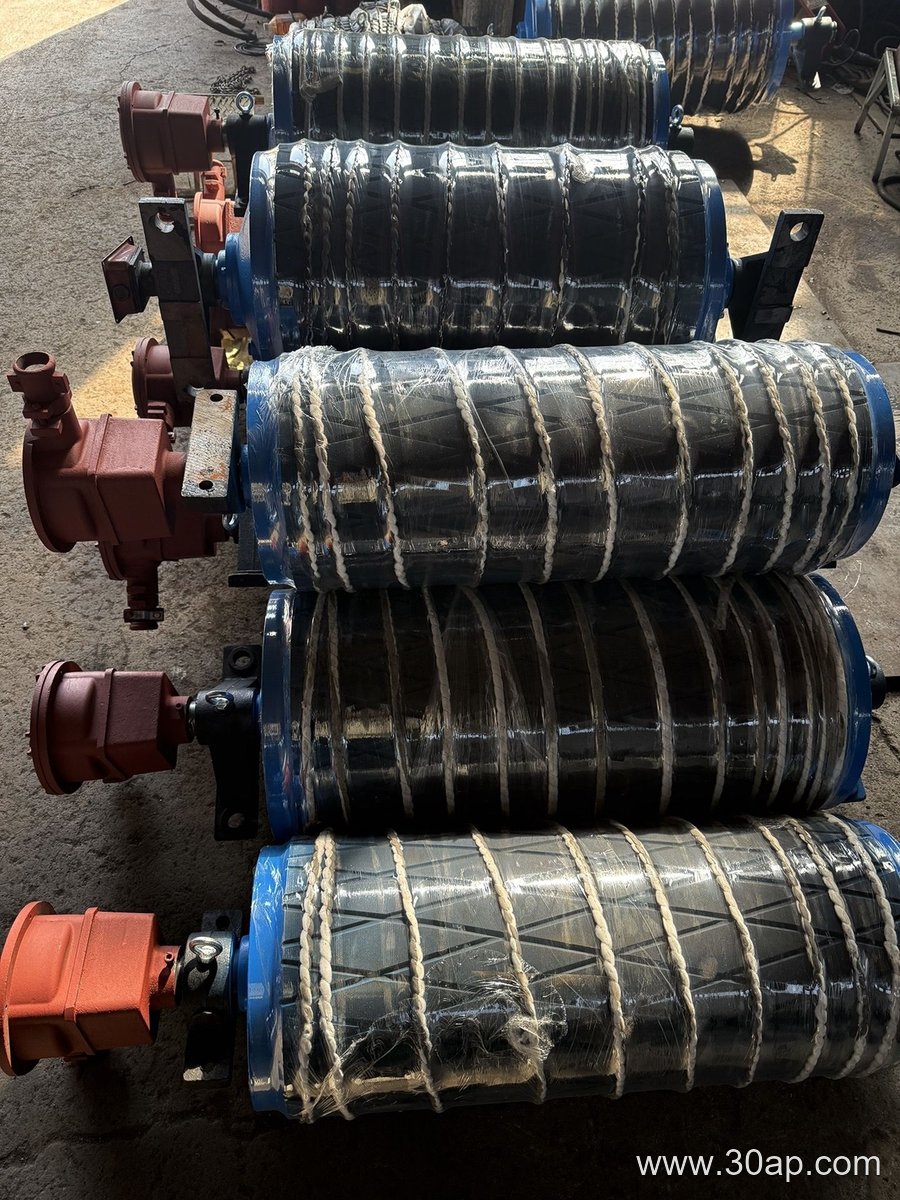
How the Lagging Is Built
The base is a welded steel drum with a shaft, hubs, and end discs. Lagging is applied to the outer surface in several common forms:
- Hot-sulphurised rubber, bonded under heat and pressure for a strong, seamless cover
- Cold-bonded rubber, applied with adhesive and often chosen for field repair
- Diamond or herringbone grooved rubber, which channels water and fines away from the contact patch
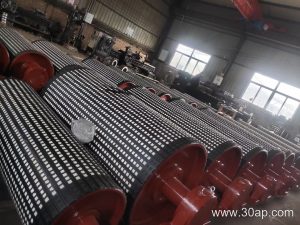
- Ceramic lagging, with embedded tiles for high-wear, high-torque duty
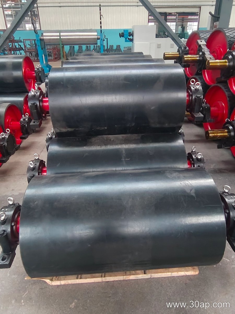
- Plain rubber, a smooth cover used where moderate grip is enough
Common lagging thickness values are 8, 10, 12, 15, and 20 mm. Grooved and ceramic surfaces are usually selected when the belt runs wet or carries sticky material. A smooth cover is simpler and easier to clean.
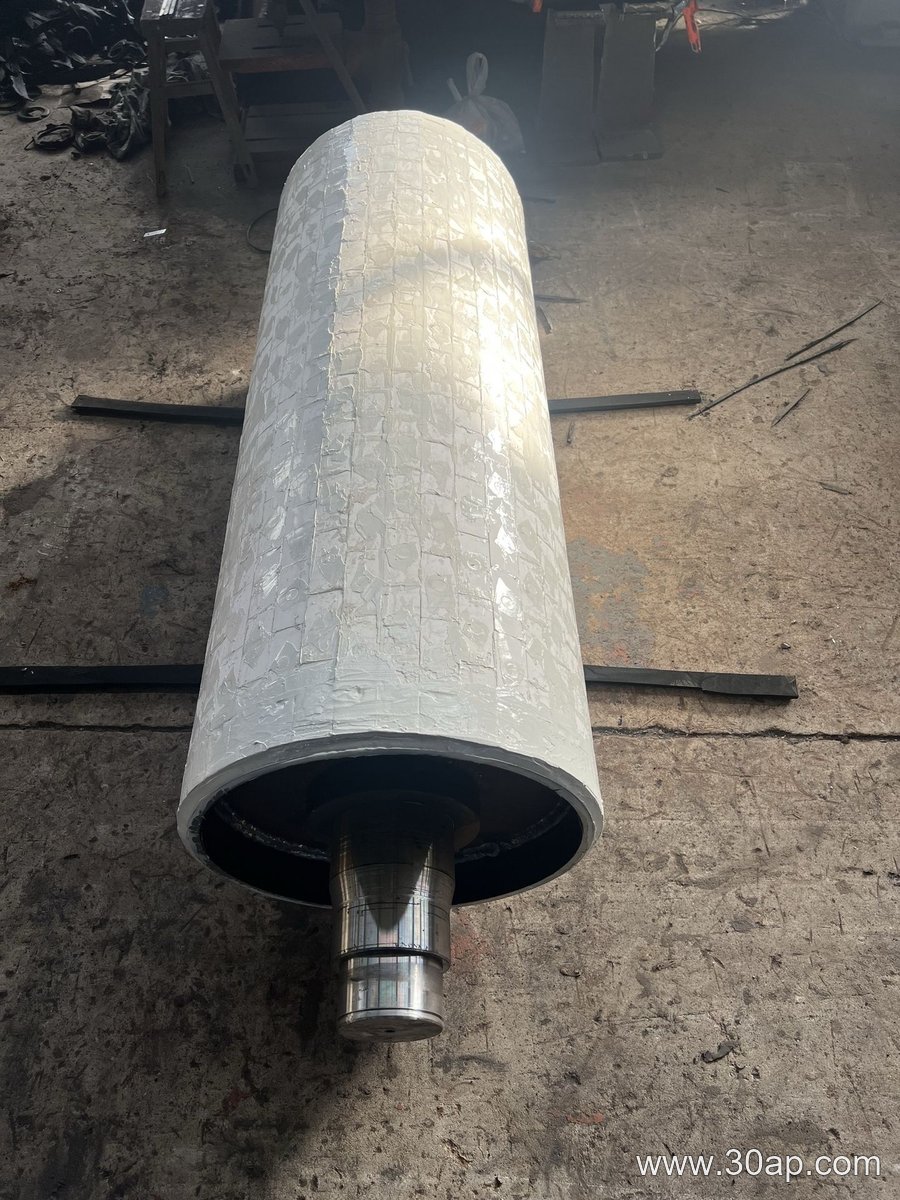
Typical Sizes and Arrangements
Shell diameter and face width are chosen from belt width, belt tension, and the torque the drive must deliver. The table below shows common reference combinations, not fixed rules. A given belt width can work with more than one diameter, and the final choice belongs to the conveyor designer.
| Belt width | Typical pulley face width | Example diameter |
|---|---|---|
| B500 | about 600 mm | Ø320 or Ø400 |
| B800 | about 950 mm | Ø500 or Ø630 |
| B1000 | about 1150 mm | Ø630 or Ø800 |
| B1200 | about 1400 mm | Ø800 or Ø1000 |
| B1400 | about 1600 mm | Ø1000 or Ø1250 |
Shaft diameter is determined by torque and load, not by belt width alone. Common shaft sizes include Ø80, Ø100, Ø120, Ø140, and Ø160. Larger drives on a B1400 or B1600 conveyor may use Ø180 or Ø200 shafts. The pulley face is normally wider than the belt so the belt stays centred.
Where It Is Used
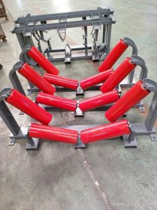
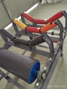
Anti-slip lagged pulleys appear wherever a conveyor must start under load or run in dirty conditions. In a sand and gravel plant, the primary drive pulley often carries the highest tension and benefits most from lagging. In a power station coal yard, wet coal can reduce friction sharply, so a grooved or ceramic cover keeps the drive from slipping. Aggregate lines, iron ore concentrators, and fertiliser plants use the same principle. A lagged drive pulley also works with the conveyor belt, idler rollers, and conveyor brackets to keep the whole system tracking and turning smoothly.
What a Buyer Should Check
Before ordering, confirm the belt width, the required torque, the shaft diameter, and the environmental conditions. Ask whether the lagging should be smooth, grooved, or ceramic, and specify the thickness if wear life matters. Check that the pulley face width matches the belt and that the shaft fits the existing bearing housings and conveyor bracket. If the pulley is a replacement, measure the old one rather than assuming a standard size. A well-chosen anti-slip lagged pulley reduces belt slip, lowers wear on the shell, and keeps the conveyor running at the designed speed.