What a Non-Standard Conveyor Bracket Is
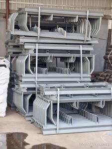
A non-standard conveyor bracket is a support component made to fit a conveyor layout that does not match a catalog standard. Instead of forcing the structure to accept an off-the-shelf part, the bracket is built around the actual belt width, trough angle, roller diameter and mounting position. In practice, the same item is often called a custom conveyor support bracket, because it is produced from a drawing or a site measurement rather than selected from a fixed list.
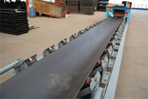
The bracket carries the idler roller or the return roller and holds it at the correct height and angle relative to the conveyor belt. It also transfers the load from the rollers into the conveyor frame. When a transfer point, a curved section or a short head section needs a special geometry, a non-standard bracket is usually the simplest way to solve the problem.
How It Is Built
Most non-standard brackets are fabricated from angle steel, channel steel or folded steel plate. The choice depends on the load, the span between supports and the available space. A typical bracket includes a base plate, one or two vertical supports, roller mounting slots or holes, and a cross member that sets the trough angle.
Because the item is custom, the mounting hole spacing and the cross member length change with the belt width and the trough angle. They should not be treated as fixed numbers. The fabricator normally works from a drawing that shows the frame connection, the roller position and the required clearance.

Where It Is Used
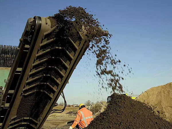
Custom support brackets appear in many bulk handling sites. Two common examples are a crushed stone plant and a coal washing plant. In a crushed stone plant, they are often used at the discharge of a crusher, where the belt width and the roller position do not match a standard frame. In a coal washing plant, they may be used on a short transfer conveyor where space is tight and the trough angle must be adjusted to keep the load centered.
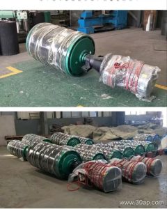
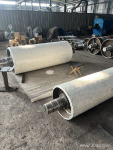
They also fit fertilizer plants and grain silos, where the material is lighter but the belt path still needs accurate support. In each case, the bracket is designed around the conveyor pulley, the idler roller and the belt line, not around a fixed catalog size.
Types and Adjustability
Non-standard brackets can follow several support styles. Common examples include troughing brackets, transition brackets, return brackets, V-return brackets, impact brackets and self-aligning brackets. An adjustable bracket is a useful variant, because it can be set to different trough angles. Typical trough angles are 20 degrees, 30 degrees, 35 degrees and 45 degrees. A forward tilt of about 1.5 degrees to 2 degrees is also used on some training brackets.
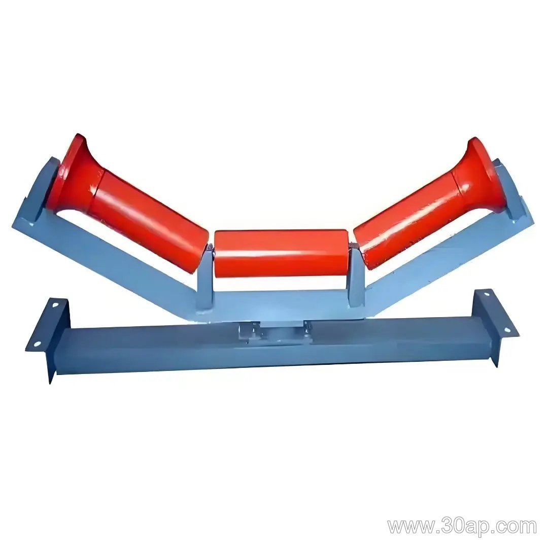
For comparison, a standard troughing bracket is made for a fixed angle and a fixed roller spacing. A non-standard bracket is made when that fixed geometry does not fit the frame or the belt path. The two are related, but they are not interchangeable.
Matching Belt Width and Roller Diameter
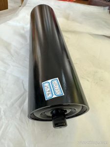
Belt width and roller diameter are selected together with the bracket. A wider belt usually needs a longer cross member and a stronger base, while the roller diameter affects the mounting height. Common belt widths include B500, B650, B800, B1000, B1200, B1400, B1600, B1800, B2000 and B2200. Common roller diameters include 89 mm, 108 mm, 133 mm, 159 mm and 194 mm.
These values are reference data, not a fixed rule. For example, a B800 belt at 35 degrees may use a 108 mm roller, while a B1200 belt at 45 degrees may use a 133 mm roller. Other combinations are possible when the load and the frame design allow it. A single belt width does not have only one possible roller diameter, and a single roller diameter does not dictate the belt width.
| Belt width | Typical trough angle | Typical roller diameter |
|---|---|---|
| B650 | 30 degrees | 89 mm |
| B800 | 35 degrees | 108 mm |
| B1200 | 45 degrees | 133 mm |
What a Buyer Should Know
- Provide the belt width, the trough angle and the roller diameter before asking for a quote.
- Send a drawing or a clear photo of the frame connection, including the mounting hole positions.
- State whether the bracket is for a carrying side, a return side or a transition point.
- Confirm the material and the surface treatment, because a wet or dusty site may need a different finish.
- Check the clearance around the conveyor pulley and the idler roller so the bracket does not touch the belt.
- Ask for the actual mounting dimensions after fabrication, since they follow the design and are not universal.
A non-standard conveyor bracket is a practical answer when a conveyor frame, a belt width or a roller position falls outside the standard range. With the right drawing and the right reference data, it can support the belt, hold the roller and keep the line running without forcing the structure into a shape it was not built for.