What Pulley Custom Machining Covers
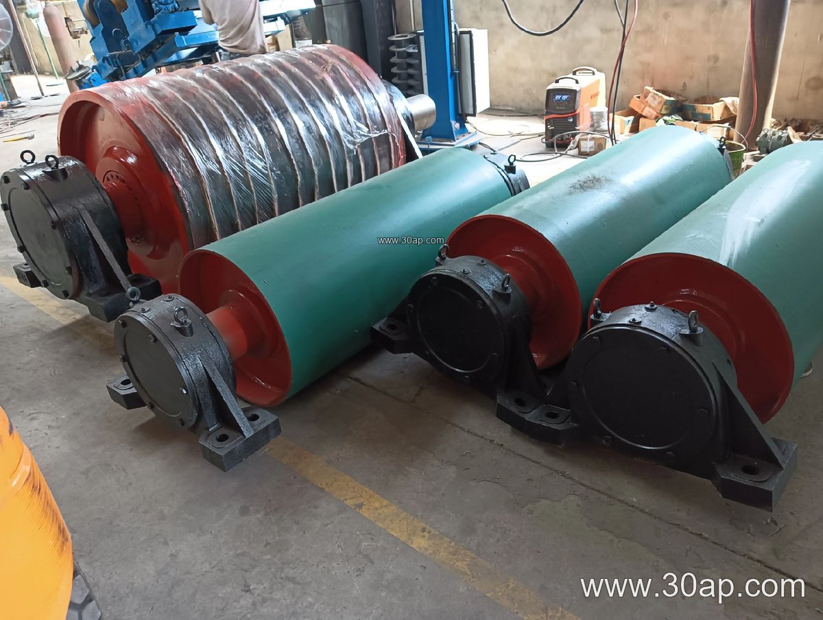
Pulley custom machining is the engineering and manufacturing work that turns a standard conveyor pulley into a component matched to one specific conveyor line. Rather than ordering a stock drum and adapting the structure around it, the buyer specifies the duty, the belt, the shaft and the face, and the pulley is machined to those inputs. The result is a conveyor pulley that fits the frame, aligns with the conveyor belt, and carries the load path the drive or take-up position was designed for.
The work usually spans three areas: the shell and end discs, the shaft and hub connection, and the lagging surface. Each is machined or prepared to drawing, then balanced and assembled. For a quarry conveyor or a power plant coal handling line, that level of fitting often decides whether the belt tracks cleanly or whether the structure has to be shimmed on site.
How a Custom Pulley Is Built
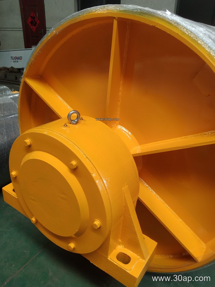
A typical build starts with the shell, which is rolled and welded, then machined at the ends to accept the discs. The shaft is turned to the required journal sizes, keyways are cut, and the hub is bored to suit. Depending on the design, the shaft may be locked with a shrink fit, a locking assembly or keys. After assembly the unit is checked for runout and balanced for the intended speed.
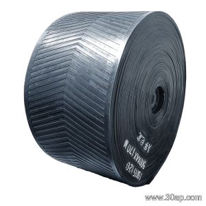
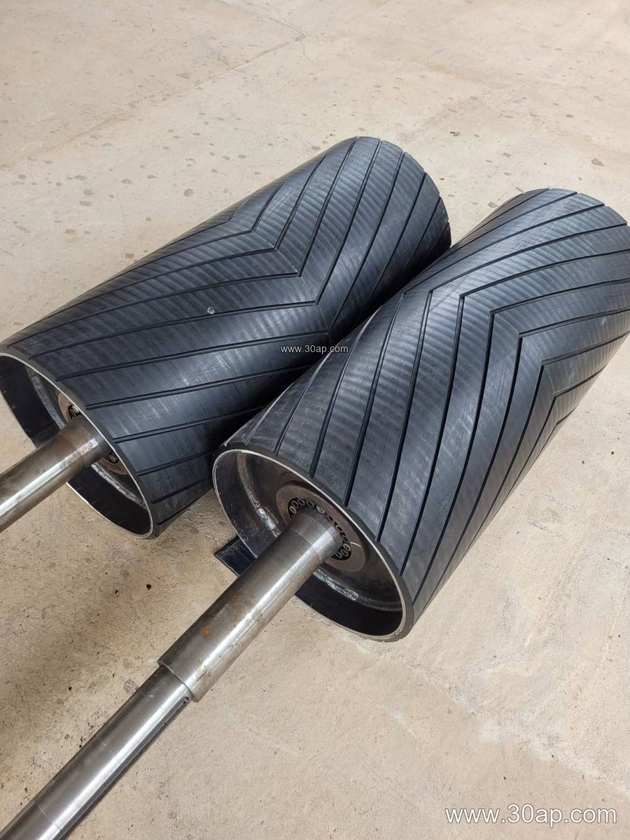
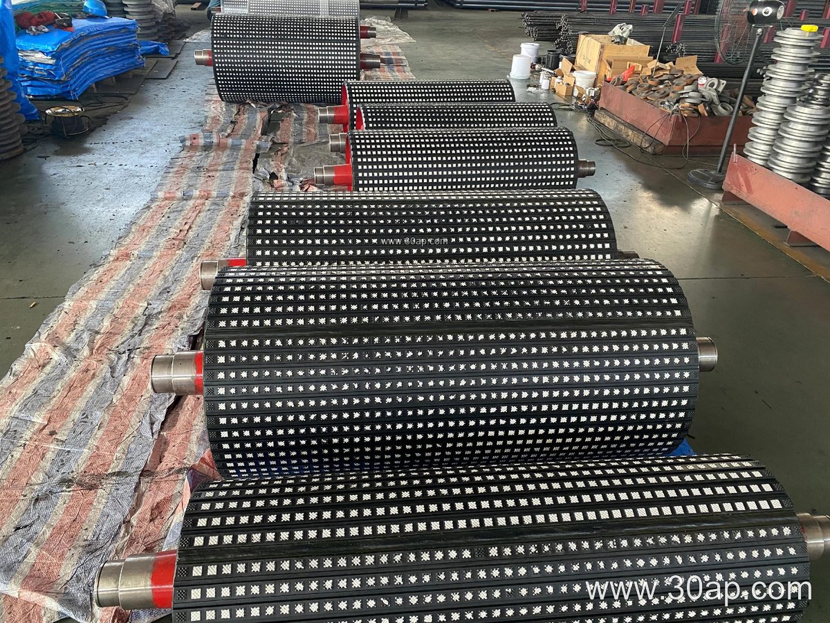
Surface preparation is where many specifications differ. Plain finish, hot vulcanized rubber, cold bonded rubber, diamond grooving, chevron grooving and ceramic tiles are all common requests. Lagging thickness is frequently quoted at 8, 10, 12, 15 or 20 mm, with the final figure set by the traction and wear conditions rather than by habit.
Common reference dimensions
Values below are typical reference points, not fixed pairings. Final sizes follow the conveyor design.
| Item | Common reference range |
|---|---|
| Belt width | B400, B500, B650, B800, B1000, B1200, B1400, B1600, B1800, B2000, B2200, B2400 |
| Pulley diameter | Ø200, Ø250, Ø315, Ø400, Ø500, Ø630, Ø800, Ø1000, Ø1250, Ø1400 |
| Face width | Usually wider than the belt, e.g. B800 about 950 mm, B1200 about 1400 mm, B1600 about 1800 mm |
| Shaft diameter | Ø50, Ø60, Ø70, Ø80, Ø90, Ø100, Ø120, Ø140, Ø160, Ø180, Ø200 |
| Lagging thickness | 8, 10, 12, 15, 20 mm |
A shaft diameter is determined by torque and bearing load, not by belt width alone. Likewise, a given belt width does not lock the pulley to one diameter; B1200 × Ø1000 and B1200 × Ø800 can both be valid for different tensions and wrap angles.
Where the Position Changes the Machining
The same shell drawing can lead to very different machining priorities depending on where the pulley sits. A drive pulley carries high torque, so the shaft, keyway and hub fit receive the most attention, and the lagging is chosen for grip. A tail pulley at the loading point sees abrasive material and impact, so a robust face and adequate disc thickness matter more than traction. A bend pulley used to increase wrap angle is usually smaller and lighter, and its balance and bearing fit dominate.
These are separate roles and are not interchangeable. A bend pulley cannot simply replace a drive pulley, and a tail pulley is not a substitute for a drive position. When a project involves both a head drive and a snub arrangement, each unit should be specified against its own duty.
Matching the Belt and the Surrounding Hardware
The belt itself shapes the request. A heavy-duty mining conveyor belt running ore at high tension calls for a larger diameter and a stronger shaft than a lighter fabric belt on a short run. On a coal mining conveyor belt with flame retardant requirements, lagging and finish choices should be consistent with the fire safety approach of the whole line. In a cement plant, a heat resistant conveyor belt on clinker service may need a pulley face that tolerates warm fines, while a food grade belt in a grain silo demands a clean, non-contaminating surface.
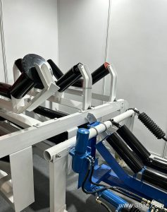
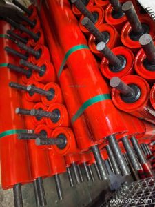
Surrounding components matter too. The conveyor bracket, the conveyor pulley bearing housing and the idler roller frames all share the same centerline, so a machined pulley that matches the drawing reduces alignment work. Face width is normally set slightly beyond the belt edge, and the transition distance to the first troughing idler affects how the belt enters the pulley.
What Buyers Should Confirm Before Ordering
- Belt width, belt type and its rated tension, since these drive diameter and shaft sizing.
- Position in the conveyor: drive, tail, bend, take-up or snub, with the expected wrap angle.
- Lagging type and thickness, plus groove pattern if traction or water shedding is needed.
- Shaft diameter, bearing centers, keyway standard and hub locking method.
- Balancing class and speed, especially for larger diameters.
- Drawing approval before machining, so bore, face and groove details are fixed.
Custom machining is not about adding complexity for its own sake. It is about giving each pulley the dimensions, surface and shaft fit its position actually needs, so the belt runs true and the structure does not have to compensate later.