What a Conveyor Support Leg Does on the Frame
A conveyor support leg is the vertical member that carries the weight of the conveyor frame, idlers, and the loaded belt down to a floor, foundation, or steel structure. In many installations it is a simple column between the stringer and the ground, but on a longer or heavier conveyor it becomes a designed structural part that controls alignment, height, and load distribution. Anyone specifying a complete conveyor system will meet this component alongside the conveyor bracket, idler roller, and conveyor pulley, and it deserves the same attention as the rotating parts.
The support leg is not a substitute for the brackets that hold the idlers. It is the part that holds the whole frame at the correct elevation and keeps the line straight over its length.
Construction and Common Materials
Most support legs are fabricated from angle steel, channel steel, or folded steel plate, then welded or bolted to a cross beam or stringer. Typical features include a base plate with bolt holes, a height adjustment slot or shim pack, diagonal bracing on taller legs, and a bolted connection at the top so the leg can be shimmed during installation.
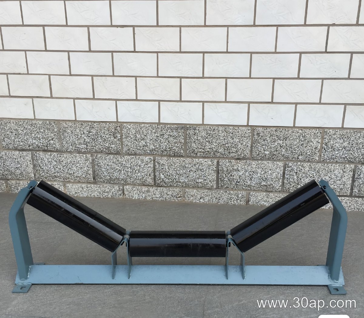
- Material options: angle steel, channel steel, folded plate
- Base: welded plate with anchor holes, sometimes with a slotted foot for fine height setting
- Bracing: fixed gusset or adjustable tie for tall supports
- Finish: painted or galvanized, chosen for the site environment
Fabricators usually match the leg section to the load path rather than to a single belt width, so two conveyors of the same width may need different leg sizes if one carries dense ore and the other carries light aggregate.
Where Support Legs Are Used
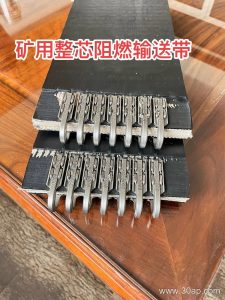
Support legs appear wherever a conveyor runs above grade. In a quarry or aggregate line they stand under the transfer points and along the inclined sections that feed a crusher. In a coal handling plant or power station coal yard they carry the frame of a long overland conveyor, often beside a flame retardant conveyor belt and a heavy-duty idler set. In a cement plant they support clinker and raw meal conveyors, and in a port or ship loading system they form the tall trestles that lift the belt to the loading boom.
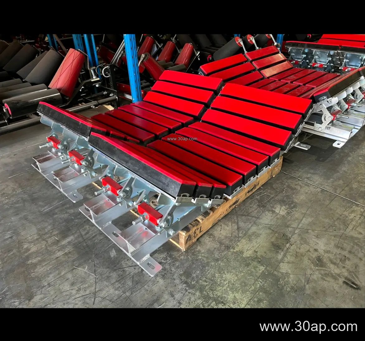
Two site types are worth a closer look. At a limestone quarry, legs are often anchored to concrete plinths so that the frame stays level after blasting vibration and seasonal ground movement. In a coal preparation plant, legs are frequently bolted rather than welded so that sections can be removed for belt replacement or maintenance access.
Matching the Leg to Belt Width, Trough Angle, and Roller Diameter
The support leg must suit the frame it carries, and the frame is defined by belt width, trough angle, and roller diameter. Common belt widths run from B500 and B650 through B800, B1000, B1200, B1400, B1600, and up to B1800 or B2000 on large installations. Trough angles of 20, 30, 35, and 45 degrees are used, and return idlers are often smaller in diameter. Typical roller diameters include Ø89, Ø108, Ø133, Ø159, and Ø194.
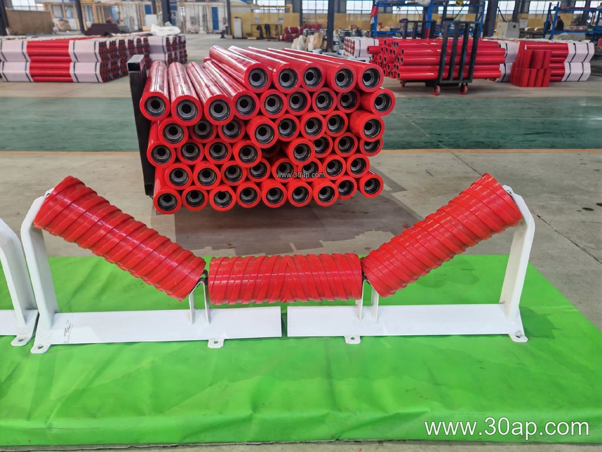
The table below shows only common reference combinations; they are not fixed rules, and the final leg height, hole spacing, and cross beam length are determined by design.
| Reference combination | Typical application | Notes for the leg |
|---|---|---|
| B650, 30 degrees, Ø89 | Small aggregate or sand line | Light frame, short legs, simple base plate |
| B800, 35 degrees, Ø108 | General quarry or cement conveyor | Medium section, bolted top connection |
| B1000, 35 degrees, Ø133 | Coal handling and power plant feed | Taller trestles, bracing recommended |
| B1200, 45 degrees, Ø133 | High-capacity ore or overland line | Deep trough, wider cross beam, heavier leg |
| B1400, 35 degrees, Ø159 | Heavy bulk material transport | Reinforced base and diagonal ties |
A single belt width does not dictate one trough angle or one roller diameter. The combination is set by capacity, material, and the idler frame design, and the support leg is then sized to that frame.
Fixed, Adjustable, and Special Support Legs
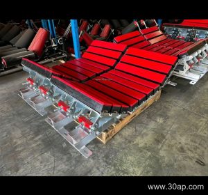
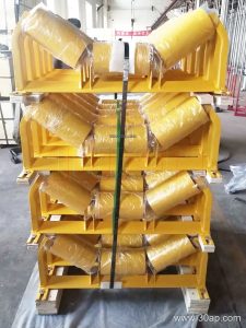
Fixed legs are welded to a set height and are simple and rigid. Adjustable legs include a slotted or telescoping section so the frame height can be corrected after the foundation settles. For transition zones between a pulley and the first idler station, a transition support leg may be shorter or angled to follow the belt path. Impact zones near a loading point often use a heavier leg under the buffer idler bracket, while self-aligning idler brackets may need a slightly wider top plate. These are variations of the same support leg family, chosen by function.
What a Buyer Should Check Before Ordering
- Confirm belt width, trough angle, and roller diameter so the top plate and hole pattern match the bracket.
- State the required leg height and whether height adjustment is needed.
- Describe the foundation: concrete plinth, steel structure, or portable frame.
- Ask for the material section and finish, especially in wet or corrosive sites.
- Clarify whether bracing, anchor bolts, and shim packs are included.
- For long conveyors, request a leg layout drawing so spacing follows the load and belt sag limits.
When the support leg, conveyor bracket, idler roller, and pulley are specified together, the conveyor runs straighter and the belt lasts longer. Buyers working on a mining conveyor belt project, a cement plant upgrade, or a quarry extension can treat the leg as a structural item with its own drawing, not as an accessory chosen at the last minute.