What an Impact Idler Does at the Loading Point
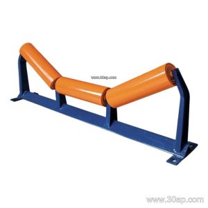
An impact idler is a buffer roller mounted beneath the conveyor belt exactly where material drops onto the system. Its job is to absorb the kinetic energy of falling rock, ore, clinker or aggregate so that the belt and the frame are not punished by every load. In a quarry conveyor line or a crushing and screening circuit, the first idler station after the chute often decides how long the belt lasts. This is why an impact idler is sometimes called a buffer roller or shock-absorbing roller, and the names describe the same component.
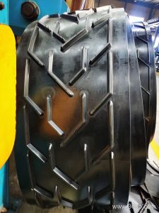
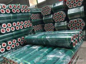
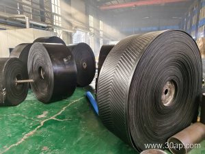
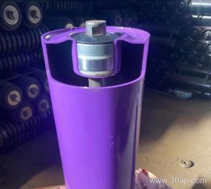
The roller body is typically a steel tube fitted with rubber rings, discs or a rubber sleeve. The rubber compresses under impact and spreads the load across a wider area of the belt, reducing point stress. Beneath the shell sits a shaft and bearing assembly, usually protected by a labyrinth or contact seal to keep out dust and water. Many plants pair these rollers with a heavy-duty conveyor belt or an abrasion resistant conveyor belt so that the belt cover and the buffer station wear at a balanced rate.
Construction Details That Affect Service Life
The rubber ring is the wearing part. Soft compounds cushion better but cut faster under sharp rock; harder compounds last longer but transmit more shock. Roller diameter matters too, since a larger shell gives more room for bearings and a lower rotational speed. Common roller diameters in buffer service include Ø89, Ø108, Ø127, Ø133 and Ø159 mm, while very heavy drop points may use Ø178 or Ø194 mm. Bearing sizes such as 6205, 6305, 6306 and 6308 appear across these diameters, but no single bearing is tied to one roller size.
Sealing quality is often underestimated. At a transfer point, dust is constant and water may be present after washing or rain. A triple-labyrinth seal with a grease retention chamber keeps the bearing running far longer than an open arrangement. Buyers should also check that the shaft ends fit the existing conveyor bracket without modification, because retrofitting a buffer station is usually a maintenance job done during a short shutdown.
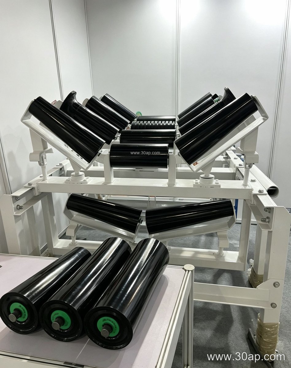
Where Buffer Rollers Fit on a Conveyor
The usual arrangement is a group of three or more cushion rollers set at the same trough angle as the carrying idlers, positioned directly under the chute. The trough angle is often 30 or 35 degrees, with 45 degrees used where the belt is wide and the load is heavy. Roller length follows belt width and trough geometry. For a three-roll trough set, common centre roller lengths are roughly 200 mm at B500, 250 mm at B650, 315 mm at B800, 380 mm at B1000, 465 mm at B1200 and 530 mm at B1400. Side rollers differ, so these are examples rather than fixed pairs.
Buffer stations appear in limestone mines, iron ore plants, copper concentrators, coal washing plants, cement kilns and clinker lines, power station coal yards, port ship loaders and concrete batching plants. In a tunnel spoil line or a gold mining operation, the drop height may be small but the material is sharp, so ring thickness and rubber hardness matter more than raw size. Where the belt also carries hot material, a heat resistant conveyor belt may be needed, and the buffer rollers should be specified with rubber that tolerates the same temperature range.
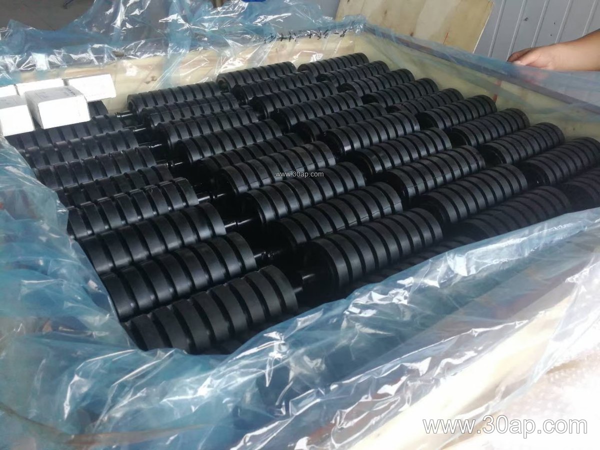
Specification Points a Buyer Should Confirm
A clear inquiry covers belt width, trough angle, roller diameter, roller length, shaft diameter, bearing type, ring material and mounting dimensions. It also helps to state the lump size, the drop height and the hourly throughput. The table below shows typical reference values; actual supply should be confirmed against the drawing.
- Roller diameter range: Ø63 to Ø219 mm; buffer service commonly Ø89 to Ø194 mm
- Belt width range: B400 to B2400 mm
- Trough angles: 20, 30, 35 and 45 degrees
- Roller surface: steel tube with rubber rings, rubber discs or rubber sleeve
- Bearing options: 6204, 6205, 6305, 6306, 6308, 6310
Do not assume that one belt width locks in one roller diameter or one shaft size. A B1200 conveyor may run Ø127 mm rollers in a light duty section and Ø159 mm rollers at the transfer point, and the shaft is chosen from the load calculation, not from the belt width alone.
Installation and Maintenance Notes
Set the buffer group so that the belt rests on the rings rather than pressing hard against a steel shoulder. Check alignment after the first shift, because a chute that discharges off-centre will wear one side of the rings quickly. Inspect for flat spots, loose rings, cracked rubber and grease leakage. Replace a roller when the rubber is worn down to the fixing band or when the bearing becomes noisy. Keeping spare rings and complete rollers on site shortens downtime in a busy aggregate plant.
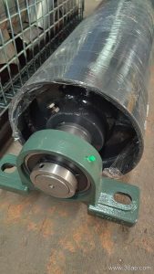
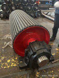
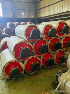
At the same transfer tower, the conveyor pulley and the drive pulley should be checked for lagging wear, since a poorly tracking belt will damage new buffer rollers within days. Matching the buffer station to the belt type, whether an EP conveyor belt, a steel cord conveyor belt or a flame retardant conveyor belt for underground use, gives the best chance of long, quiet service.