What Conveyor Pulley Welding and Machining Covers
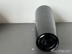
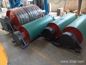
Conveyor pulley welding and machining is the fabrication stage where a rolled steel shell, shaft, and end discs are joined into a load-bearing drum, then finished to the tolerances a belt conveyor needs. In a quarry, a coal preparation plant, or a cement clinker line, this work determines whether the belt tracks straight, whether the lagging wears evenly, and how long the bearings last. A conveyor pulley is not a simple steel cylinder; it is a precision assembly that must handle tension, torque, and abrasive dust at the same time.
The two processes are linked. Welding creates the structure, and machining corrects what welding distorts. Skipping either step usually shows up later as belt mistracking, vibration, or premature lagging failure.
How the Drum Is Built
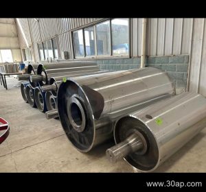
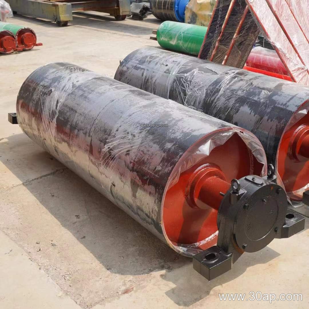
Fabrication normally starts with a rolled shell, two end discs, and a through shaft or stub shafts. The shell is welded to the end discs with full-penetration or fillet welds depending on design, and the shaft is fixed by welding, keying, or shrink fitting. After welding, the assembly is stress-relieved where the design calls for it, because heat input can pull the shell out of round.
Machining then brings the outside diameter, face width, shaft journals, and keyways into specification. The journal surfaces are turned and ground to fit bearings, and the pulley face is trued so the conveyor belt runs on a concentric surface. Dynamic balancing is common on larger or faster units.
Welding quality points
- Weld procedure and electrode selection matched to shell and shaft steel
- Controlled heat input to limit distortion of thin shells
- Dye-penetrant or ultrasonic checks on critical welds when specified
- Runout checked after machining, not only after welding
Machining quality points
- Concentricity between shaft journals and shell OD
- Correct keyway dimensions and surface finish
- Face width and edge chamfers that protect the belt
- Surface roughness suitable for bonding rubber lagging
Subtypes and Their Different Jobs
The same welding and machining discipline applies across the family, but each position on the conveyor asks something different. A drive pulley transmits torque and usually carries the heaviest lagging; a tail pulley guides the return side and often needs cleaning-friendly surfaces; a bend pulley changes belt direction without driving. These are separate roles and are not interchangeable. A wing pulley, used for self-cleaning in sticky material, is another distinct subtype and appears here only as a contrast, not as a substitute for a standard drum.
Common combinations seen in project drawings include B800 × Ø500, B1200 × Ø1000, and B1400 × Ø800. Diameter is chosen from belt tension, wrap angle, and space, not from belt width alone. Shaft diameter is sized from torque and load, so a B1000 pulley may run a Ø120 shaft in one duty and a larger journal in another.
Where the Work Matters Most
In a limestone quarry or an aggregate crushing and screening line, dust and grit attack every joint. A well-machined shell with tight runout keeps the abrasion resistant conveyor belt centered and reduces edge wear. In a power plant coal handling system, a flame retardant conveyor belt runs beside pulleys that must stay true under continuous load. In a cement plant, heat and fine powder make lagging bond quality critical, which is why the machined surface under the rubber matters as much as the weld.
Heavy-duty mining conveyor belts, including steel cord conveyor belt designs and high-tension EP conveyor belt constructions, place higher radial loads on the shell and shaft. That pushes fabricators toward thicker shells, full-penetration welds, and more careful balancing.
Specification Reference
The values below are typical reference data, not fixed rules. Final dimensions follow the conveyor design.
| Item | Common range |
|---|---|
| Belt width | B400, B500, B650, B800, B1000, B1200, B1400, B1600, B1800, B2000 |
| Pulley diameter | Ø200, Ø250, Ø315, Ø400, Ø500, Ø630, Ø800, Ø1000, Ø1250, Ø1400 |
| Face width | Usually wider than belt, e.g. B800 about 950 mm, B1200 about 1400 mm |
| Shaft diameter | Ø50 to Ø200 depending on torque |
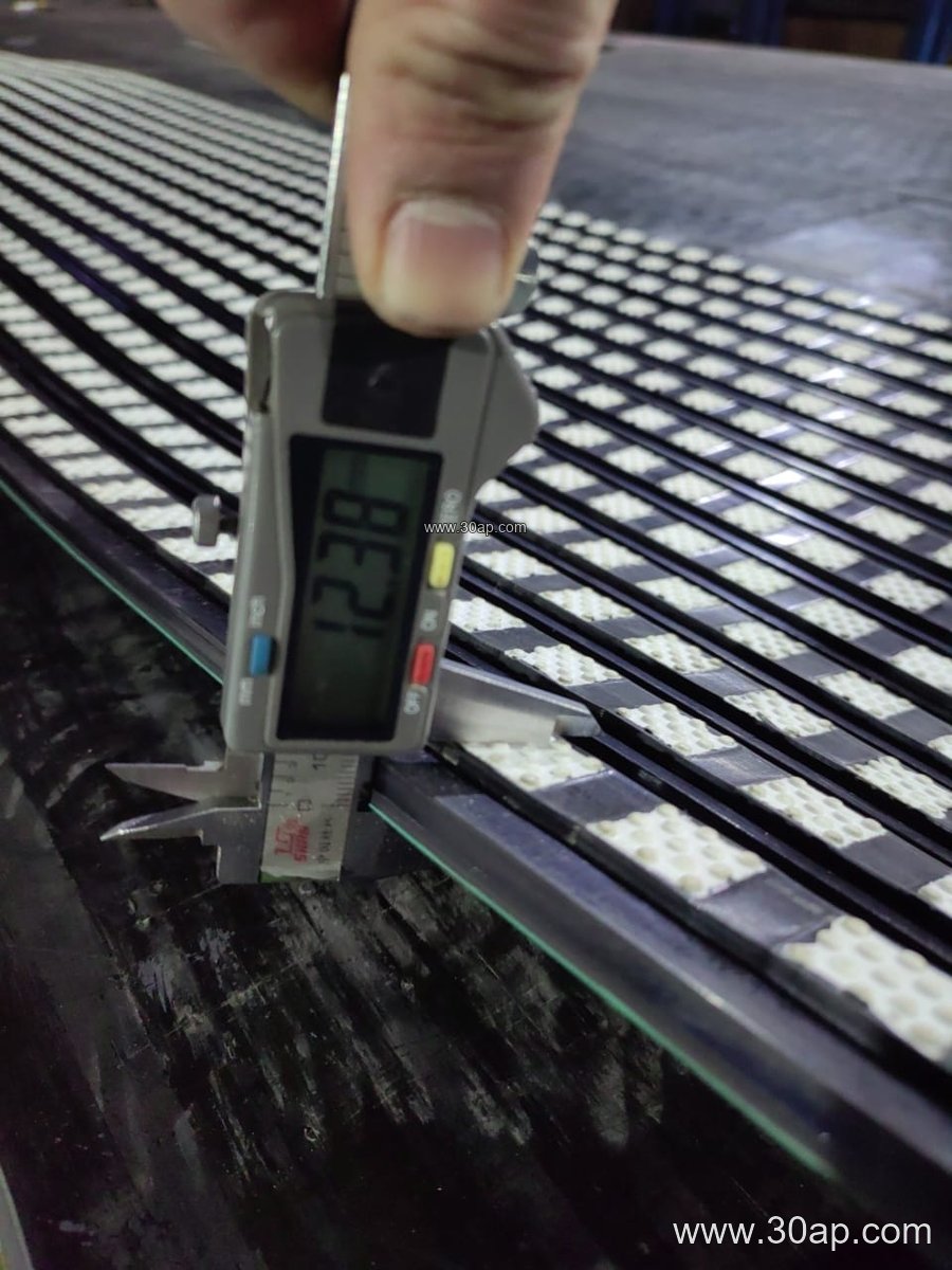
| Lagging thickness | 8, 10, 12, 15, 20 mm |
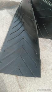
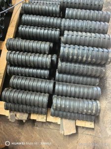
| Surface forms | Plain, hot-vulcanized rubber, cold-bonded rubber, diamond, chevron, ceramic |
What Buyers Should Check
Ask for the weld procedure and the final runout report, not just a drawing. Confirm that journal dimensions match the bearing bore and that keyways are cut after stress relief. For lagging, specify the surface preparation and bond method, because a good drum with poor adhesion will shed rubber in a wet coal or slurry environment.
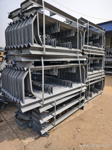
Also confirm how the pulley interfaces with the conveyor bracket and the conveyor pulley support structure, and whether the shaft end is designed for a take-up frame. For high-abrasion duties such as iron ore or copper ore handling, ceramic or diamond lagging is often worth discussing. For food or clean material, a plain machined face may be preferable.
Finally, request concentricity and balance records for large diameters, and check that the face width suits the actual belt, including any skirted or corrugated sidewall conveyor belt that needs extra clearance. Matching a pulley to the belt is a design exercise, not a lookup table.