What an Ore Conveyor Pulley Does on a Bulk Handling Line
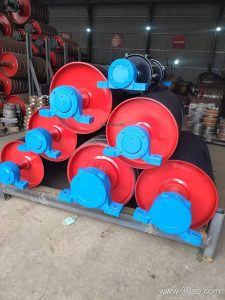
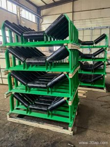
An ore conveyor pulley is the rotating drum that drives, tensions, or redirects the belt on a bulk material conveyor. In a crushing circuit or a sintering plant, the pulley has to transfer drive torque into an abrasive, often heavy load while keeping the belt tracking true. Because ore is dense and sharp-edged, the drum body, shaft, and lagging are usually built heavier than on a general-purpose conveyor. The pulley works together with the conveyor belt and the idler roller set, but it is the component that carries the highest concentrated belt tension.
Although the term covers the whole family, the position on the conveyor decides the duty. A drive pulley transmits power; a tail pulley returns the belt; a bend pulley changes direction. These are separate roles and are not interchangeable, even when they look similar from the outside.
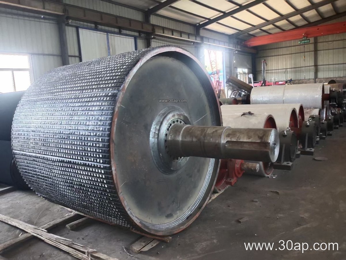
Construction Details That Matter Underground and in the Mill
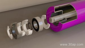
Most ore conveyor pulleys use a welded steel shell with dished or flat end plates, keyed to a through shaft. The shell is machined to keep runout small, because vibration shortens bearing life and damages the belt edge. Shaft diameter is set by torque and radial load, not by belt width alone, so a B800 and a B1200 machine can share a shaft size if the duty is light, while a heavily loaded B1000 unit may need a much larger shaft. Common shaft sizes include Ø80, Ø100, Ø120, Ø140, and Ø160 mm, with larger diameters for high-tension drives.
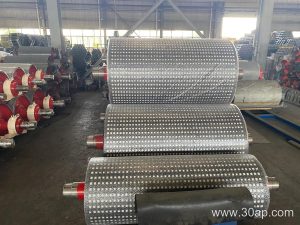
Surface treatment is where ore duty is won or lost. Plain shells slip when the ore is wet; lagging restores grip. Cast rubber, cold-bonded rubber, hot-vulcanized rubber, diamond groove, herringbone, and ceramic lagging are all used, with common lagging thicknesses of 8, 10, 12, 15, and 20 mm. In a coal preparation plant, a flame retardant conveyor belt is often specified, and the lagging should be chosen to match that fire-safety approach. Ceramic tiles suit wet, abrasive iron ore transfer points, while diamond rubber is a practical general choice.
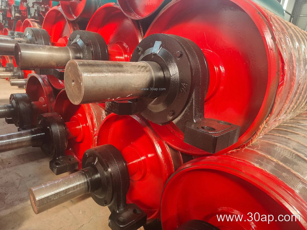
Reference Dimensions and Typical Combinations
The table below lists reference values only. They are not fixed pairings, and final dimensions are confirmed by the conveyor designer.
| Belt width | Typical pulley face width | Common diameter range |
|---|---|---|
| B500 | about 600 mm | Ø250 to Ø400 |
| B650 | about 750 mm | Ø315 to Ø500 |
| B800 | about 950 mm | Ø400 to Ø630 |
| B1000 | about 1150 mm | Ø500 to Ø800 |
| B1200 | about 1400 mm | Ø630 to Ø1000 |
| B1400 | about 1600 mm | Ø800 to Ø1250 |
| B1600 | about 1800 mm | Ø1000 to Ø1400 |
Face width is normally wider than the belt so the belt can wander slightly without running off the shell. Combinations such as B800 × Ø500, B1200 × Ø1000, and B1400 × Ø800 are common in practice, but no single belt width locks a pulley to one diameter. For very high tensions, as in a long overland iron ore line, a steel cord conveyor belt may be paired with a large drive drum, while a shorter aggregate conveyor might use an EP conveyor belt or NN conveyor belt with a moderate diameter.
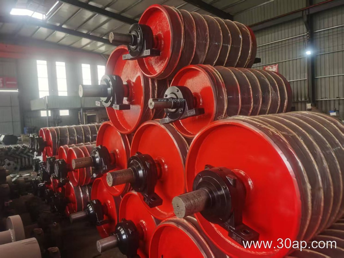
Where These Pulleys Are Installed
In a limestone quarry or a sand and aggregate line, the ore conveyor pulley is usually found at the head of the primary discharge and at the tail tension station. In a copper concentrator, bend pulleys redirect the belt around the drive house. In a power plant coal yard, a flame retardant conveyor belt and a lagged drive pulley handle the fuel feed. Underground coal mining conveyor systems place the drive pulley in a confined transfer station, where compact bearing housings and easy lagging replacement matter as much as raw strength.
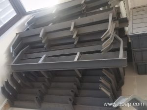
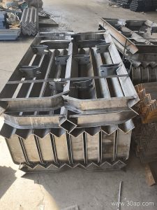
Layout also includes the conveyor bracket that fixes the bearing housing to the frame, so alignment between pulley, bracket, and belt centerline should be checked at installation. In a cement plant clinker line, heat and dust push buyers toward heat resistant conveyor belt grades and dust-tight bearing seals.
Buyer Checklist Before Ordering
- Confirm the role: drive, tail, or bend. Do not substitute one for another.
- State belt width, belt type, and expected tension so the shell and shaft can be sized properly.
- Choose lagging by material: wet ore, oil carry-back, heat, or fine dust each favors a different surface.
- Specify shaft diameter from torque and load calculations, not from belt width alone.
- Ask for machining tolerance, balancing class, and bearing type in writing.
- Plan a maintenance window for lagging inspection, since worn lagging reduces grip and increases belt slip.
For a full conveyor package, buyers often source the ore conveyor pulley together with the conveyor belt, idler roller, and conveyor bracket from one supplier to keep interfaces consistent. Matching an abrasion resistant conveyor belt to a well-lagged drum is usually cheaper than replacing a slipping belt later.