On a wet outdoor stockpile, a conveyor belt that slips during startup is a common and frustrating fault. The belt may creep, stall, or emit a high-pitched squeal while the drive pulley spins. This symptom is often blamed on the belt itself, but the root cause can lie in several interacting factors. Understanding these distinctions is essential for a correct repair.
Recognizing the Symptoms of a Slipping Conveyor Belt
A slipping conveyor belt typically shows one or more of these signs: reduced or zero material throughput, a polished or glazed pulley surface, rubber dust around the drive, and a belt that stops moving while the motor continues to run. In wet conditions, the slip is often worse at startup or after a rain shower. These symptoms are your first clue to the cause.
Plausible Causes and How to Distinguish Them
1. Moisture Between Belt and Pulley
Water acts as a lubricant, reducing the friction coefficient. This is the most obvious cause in an outdoor setting. Check for water pooling on the belt return side or a wet pulley lagging. If the slip disappears after the belt runs empty for a few minutes, moisture is likely the main culprit.
2. Insufficient Belt Tension
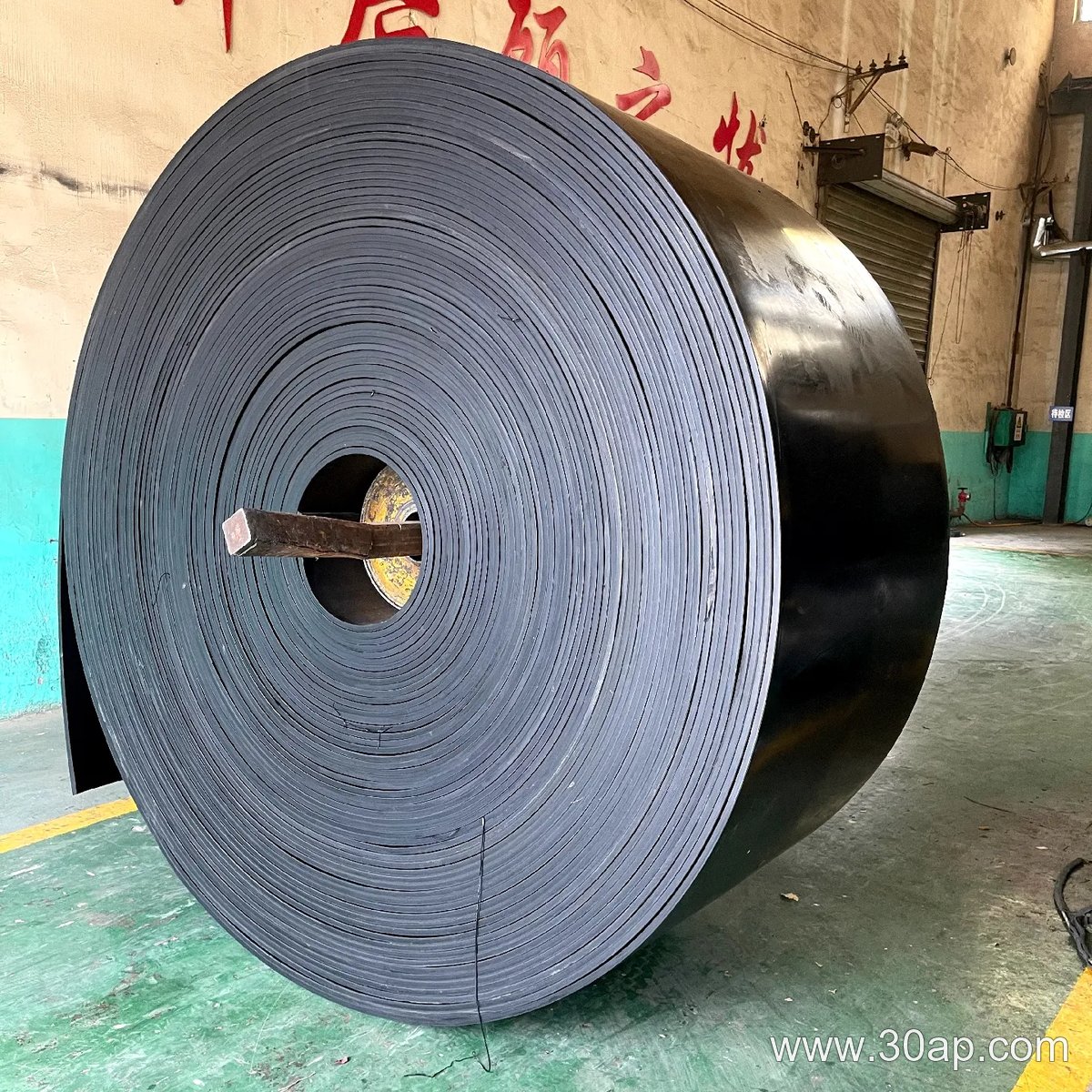
Low tension reduces the normal force that presses the belt against the drive pulley. A telltale sign is that the belt slips under load but runs fine empty. Measure the sag at the take-up; if it exceeds the manufacturer’s recommendation, adjust tension.
3. Worn or Glazed Pulley Lagging
Over time, rubber lagging can become hard, shiny, or contaminated with oil. This reduces friction even when dry. Inspect the lagging for cracks or a glassy appearance. If the lagging is worn, the belt may slip regardless of tension or moisture.
4. Overloading or Material Buildup
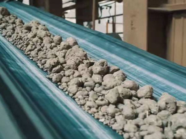
In a wet stockpile, material can stick to the belt and create an uneven load. This increases the required drive force. Look for lumps of wet material on the return rollers or a belt that tracks poorly. A sudden slip after a heavy rain may point to this cause.
Practical Actions to Stop the Slipping
- Install or repair a belt cleaner to remove wet, sticky material.
- Add a drainage path or a roof over the drive station if feasible.
- Re-tension the belt according to the manufacturer’s manual.
- Replace glazed or worn pulley lagging with a grooved or ceramic-lagged pulley.
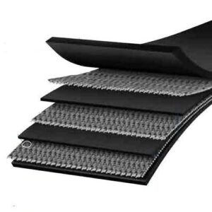
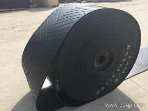
- Consider a belt with a higher friction cover for wet duty, if the application allows.
By separating moisture, tension, lagging, and load effects, you can diagnose the fault accurately and avoid replacing a conveyor belt that is not the real problem.
How to Read an Idler Roller Specification Sheet for a Cement Plant Conveyor
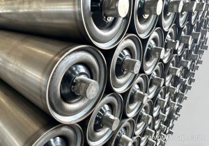
In a cement plant, an idler roller must survive abrasive clinker dust, heat, and continuous duty. A specification sheet is not a marketing brochure; it is a set of engineering fields. Reading it correctly means knowing which units apply and where a value is a nominal dimension rather than a guaranteed rating. The following explains common fields without assuming any particular standard or manufacturer.
Tube Diameter and Wall Thickness
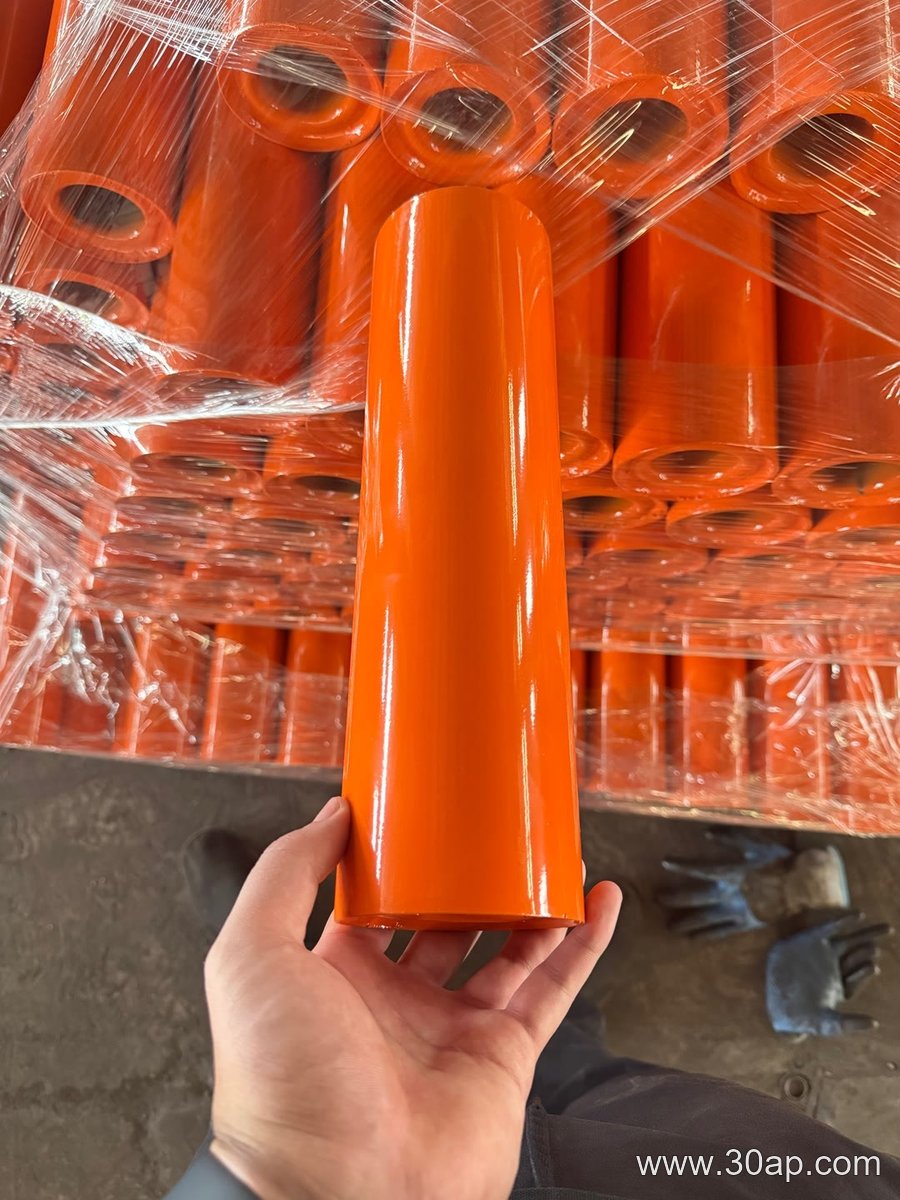
Tube diameter is usually given in millimeters (mm), often preceded by the Ø symbol—for example, Ø127 means a nominal outside diameter of 127 mm. This dimension affects belt contact and load distribution. Wall thickness, also in mm, indicates the tube’s resistance to bending under load. A thicker wall is not automatically better; it changes weight and bearing load. Always treat these as nominal values unless the sheet states a tolerance.
Roller Length and Shaft Dimensions
Roller length (mm) defines the face width that supports the belt. Shaft diameter (mm) and shaft length (mm) determine how the idler roller mounts to the frame. The shaft may be specified with a thread size, a flat, or a keyway. These are interface dimensions: they must match the bracket or frame, and a mismatch is a common cause of premature wear or noise.
Bearing Type and Sealing
Bearing designation often appears as a number or a code (for example, a deep-groove ball bearing size). Sealing is described by type—such as labyrinth, contact lip, or felt—not by a universal IP rating. In a cement plant, the seal choice matters more than the bearing brand because fine dust penetrates non-contact seals. The sheet may list a clearance or a grease fill, but these are nominal and should be confirmed for the actual duty.
Load, Speed, and Temperature Fields
Load capacity is typically stated in newtons (N) or kilonewtons (kN), often as a radial load at a given speed. Speed may appear in revolutions per minute (rpm) or as a maximum belt speed in meters per second (m/s). Temperature limits are given in degrees Celsius (°C). These values are interdependent: a load rating at 500 rpm does not apply at 1,500 rpm. If the sheet lists a single figure, treat it as a reference point, not a universal guarantee.
Reading Example: A Hypothetical Cement Plant Check
Suppose a specification sheet for an idler roller shows Ø127 mm tube, 4.5 mm wall, 380 mm roller length, 25 mm shaft diameter, a 6205 bearing code, and a load rating of 2.5 kN at 800 rpm. A maintenance engineer would first verify that the shaft fits the existing frame, then check that the seal type suits clinker dust, and finally confirm that the actual belt speed and load fall below the stated reference values. No single field is a pass or fail; the set must be compared with the conveyor’s operating conditions.
- Always note the unit: mm, N, kN, rpm, m/s, or °C.
- Distinguish nominal dimensions from rated capacities.
- Confirm interface dimensions before ordering.
- Match seal type to the dust and moisture environment.
Reading an idler roller specification sheet is an exercise in matching fields to context, not in memorizing numbers. In a cement plant, that context includes abrasive dust, heat, and continuous operation, so the seal and shaft interface often deserve as much attention as the load rating.
Why Manufacturing Sequence Matters for Conveyor Pulley Performance
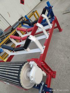
In a mineral-processing plant, a conveyor pulley is not simply a drum that turns. It is a structural assembly built to carry belt tension, resist abrasion, and maintain alignment under constant load. Two pulleys with identical dimensions can perform very differently depending on how they were manufactured. This article traces the key production stages and explains how each one affects the finished quality of a conveyor pulley.
Shell Forming and Welding: The Foundation of Pulley Strength
The shell begins as rolled steel plate. The rolling process determines roundness and wall thickness uniformity. A shell that is out-of-round will cause belt tracking problems and uneven lagging wear. After rolling, longitudinal seams are welded. Weld quality matters because the shell acts as a beam under belt tension. Poor penetration or excessive distortion can create stress concentrations that lead to fatigue cracking. In mineral processing, where pulleys often face continuous heavy loads, a well-formed and properly welded shell is essential.
Machining of Hub and Shaft Interfaces
Hubs are machined to accept the shaft and to transfer torque from the shell. The fit between hub and shaft—whether interference fit or keyed—must be precise. A loose fit can cause fretting, vibration, and premature failure. Machining tolerances also affect how well the pulley can be balanced. For high-speed conveyors in a mineral plant, imbalance leads to bearing wear and reduced service life.
Lagging Application: More Than a Wear Surface
Lagging is applied to the shell to increase friction between pulley and belt. The manufacturing method—vulcanized rubber, ceramic tiles, or grooved rubber—influences grip, wear resistance, and cleanability. In dusty mineral-processing environments, lagging that is improperly bonded can peel away, causing belt slip and downtime. The bonding process, including surface preparation and curing, directly affects lagging life.
Balancing and Final Inspection
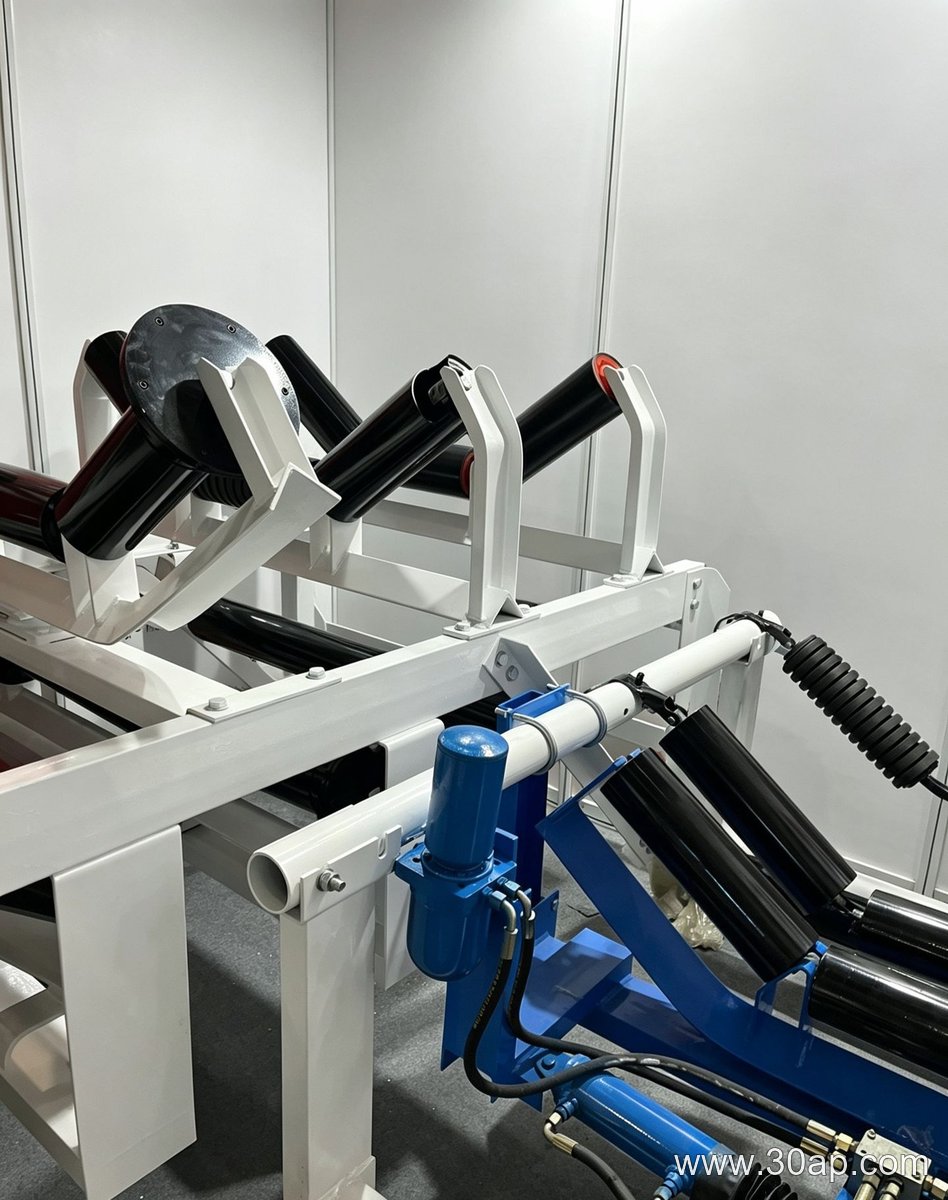
After assembly, the conveyor pulley is dynamically balanced. This step reduces vibration and extends bearing life. Final inspection checks runout, concentricity, and surface finish. A pulley that passes dimensional checks but fails balance will still perform poorly. In a mineral-processing plant, where uptime is critical, these final stages separate a reliable conveyor pulley from a problem component.
FAQ: Manufacturing Effects on Conveyor Pulley Quality
How does welding affect conveyor pulley life?
Welding affects fatigue resistance. Poor welds can crack under cyclic loading, especially in heavy-duty mineral processing.
Why is lagging bonding important?
Bonding determines whether lagging stays in place. Poor bonding leads to slip and accelerated wear.
What role does balancing play?
Balancing reduces vibration, which protects bearings and improves belt tracking.
Improving Conveyor Bracket Abrasion Resistance on a General Manufacturing Line
A conveyor bracket does not usually fail because the belt is too heavy. It fails because fine, hard particles work their way into the contact points where the bracket meets the idler roll, the frame, or the mounting bolts. Once those particles are trapped, every small vibration turns them into a grinding paste. The result is a slow loss of section thickness, wallowed bolt holes, and eventually a bracket that no longer holds alignment.
The practical goal is not to make the conveyor bracket infinitely hard. A very hard bracket can become brittle and crack under shock. The goal is to choose a surface condition and geometry that shed abrasive material before it becomes embedded.
Where Abrasion Actually Attacks a Conveyor Bracket
On a general manufacturing line, abrasion is rarely uniform. It concentrates in three zones:
- Sliding contact surfaces: adjustable brackets have slots or shims that slide during alignment. Grit trapped in these gaps acts like lapping compound.
- Bolt head seats: dust accumulates around fasteners and is compacted by vibration, wearing away the bracket face.
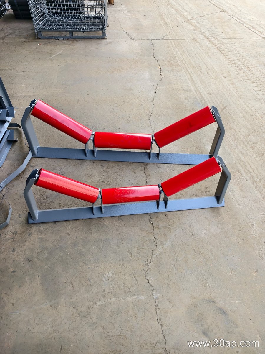
- Idler seating pockets: the cradle that holds the idler shaft can collect material that rotates with the roll.
A conveyor bracket with generous radii, open drainage, and no deep pockets will shed material instead of storing it. That is a geometry decision as much as a material decision.
Material and Coating Choices for Abrasive Service
For mild abrasive exposure, a painted or powder-coated carbon steel conveyor bracket can perform adequately if the coating remains intact. Once the coating is breached, however, corrosion and abrasion accelerate together. Hot-dip galvanizing offers better protection because the zinc layer sacrifices itself, but it is softer than many abrasion-resistant steels and can be worn away in high-contact zones.
For more severe sliding abrasion, a quenched-and-tempered steel or a wear-resistant plate can be used in the bracket body, though welding and forming become more demanding. A useful compromise is a carbon steel conveyor bracket with replaceable wear pads or hardened bolt washers at the contact points. This keeps the main bracket inexpensive while placing abrasion resistance only where it is needed.
Practical Steps for a General Manufacturing Line
Start by inspecting used brackets and identifying the actual wear pattern. If wear is concentrated at bolt seats, add hardened washers or increase the bearing area. If the idler pocket is the problem, open the pocket and add a drainage slope. If the entire bracket face is thinning, consider a harder alloy or a replaceable liner.
Finally, keep the area clean. A conveyor bracket that is regularly cleared of accumulated grit lasts far longer than one that is left to self-clean. Abrasion resistance is partly a material property and partly a maintenance habit.