What the Main Drive Pulley Does
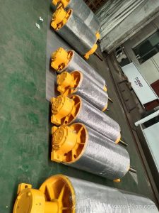
The main drive pulley is the head-end drum that transmits motor torque to the conveyor belt and keeps the whole system moving. Mounted at the discharge point, it grips the belt through friction between the drum surface and the belt cover, pulls the loaded strand forward, and delivers material into the chute or onto the next machine. In a cement plant clinker line or a power plant coal yard, this single component often sets the pace for the entire conveying circuit.
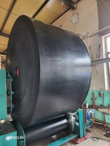
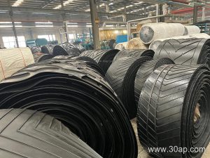
Because it carries the highest tension in the system, the drive pulley must be matched to belt strength, wrap angle and starting torque rather than chosen by width alone. A heavy-duty mining conveyor belt running ore from a primary crusher, for example, demands a different drum build than a lighter aggregate conveyor belt on a screening deck.
Construction and Surface Options
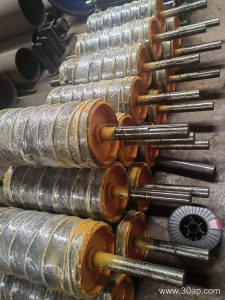
The drum body is usually a welded steel shell with machined end discs, keyed or shrink-fitted to a shaft that turns in heavy-duty bearing housings. Lagging is what converts torque into grip. Common surface forms include plain, cast rubber, cold-bonded rubber, hot-vulcanized rubber, diamond grooved, herringbone grooved and ceramic lagging, with rubber thickness typically 8, 10, 12, 15 or 20 mm.
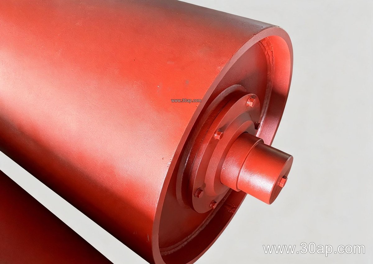
- Plain shells suit light loads and clean, dry conditions.
- Diamond or herringbone lagging improves wet-weather traction and sheds water.
- Ceramic lagging resists wear in abrasive quarry and iron ore service.
- Hot-vulcanized rubber offers a strong bond for high-torque drives.
Shaft diameter is set by torque and radial load, commonly falling in the Ø50 to Ø200 mm range, and should be confirmed by the drive calculation rather than copied from belt width.
Typical Sizes and Reference Data
The table below shows common combinations. These are reference values, not fixed pairings; final selection depends on belt tension, speed and load.
Common Diameter and Face Width References
| Belt Width | Typical Pulley Face Width | Example Diameter Combination |
|---|---|---|
| B500 | about 600 mm | B500 × Ø400 |
| B800 | about 950 mm | B800 × Ø500 |
| B1000 | about 1150 mm | B1000 × Ø630 |
| B1200 | about 1400 mm | B1200 × Ø1000 |
| B1400 | about 1600 mm | B1400 × Ø800 |
| B1600 | about 1800 mm | B1600 × Ø1000 |
| B1800 | about 2000 mm | B1800 × Ø1250 |
A wider belt does not automatically require a larger diameter, and one belt width can pair with several drum sizes depending on wrap angle and belt modulus.
Where It Fits in the Conveyor
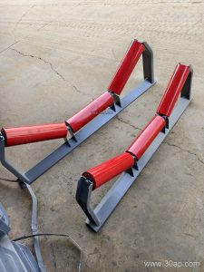
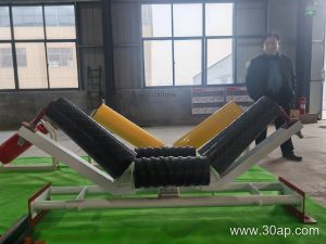
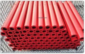
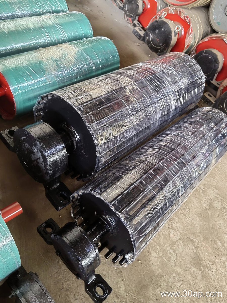
The drive drum sits at the head station, often on a fabricated conveyor bracket shared with the take-up frame and the discharge chute. It works together with carrying idler rollers, return rollers and the belt itself. On a long overland line in a copper mine, a steel cord conveyor belt may run over a Ø1250 mm drive pulley, while a shorter stone crushing conveyor belt might use a Ø500 mm drum. The tail pulley and bend pulleys only redirect or tension the belt and are not interchangeable with the drive drum.
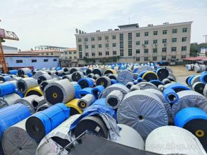
In underground coal mining, flame retardant conveyor belt and PVG conveyor belt grades are common, and the drive pulley lagging must be selected to avoid slip without damaging the cover. Similar logic applies to an abrasion resistant conveyor belt in a sand making plant.
Buyer Checklist
- Confirm belt type and tension: EP conveyor belt, NN conveyor belt or steel cord conveyor belt each needs a different drum design.
- Specify lagging form and thickness for the environment, such as oil resistant or heat resistant service.
- Provide motor power, speed, wrap angle and starting method so shaft and bearing size can be calculated.
- Check that face width exceeds belt width and that the conveyor bracket and bearing housings match the shaft.
- Plan inspection of lagging wear and bolt torque as part of routine maintenance.
For more on matching drums with rubber conveyor belt and fabric core conveyor belt systems, visit www.example.com/conveyor-pulley and www.example.com/main-drive-pulley for related reference pages.