Understanding the Conveyor Bend Pulley Function
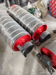
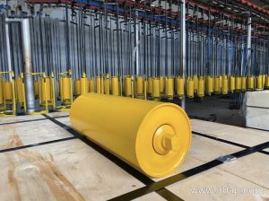
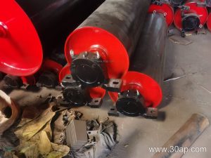
In heavy-duty bulk material handling systems found in port operations, changing the direction of the continuous loop requires precision engineering. A conveyor bend pulley redirects the belt path, increasing the wrap angle around a drive unit or navigating complex structural layouts. Unlike a primary drive or tail component, this specific redirecting roller focuses entirely on guiding the path without applying rotational torque.
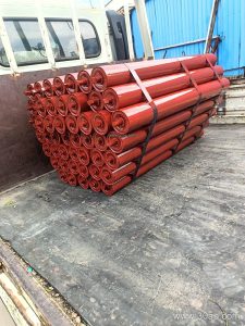
When paired with a high-capacity Steel Cord Conveyor Belt or an abrasion-resistant Multi-Ply Fabric Core Conveyor Belt, the component must endure significant radial loads. Proper alignment alongside standard idler roller assemblies and secure conveyor bracket mountings ensures that the belt transitions smoothly through the turning points without edge wear or mistracking.
Surface Coverings and Environmental Adaptation
Port terminals handle abrasive minerals, coal, and aggregates, which places immense stress on system components. Selecting the correct shell surface for a conveyor pulley prevents slippage and material buildup. Engineers often choose between plain steel surfaces and various lagging options depending on the operating environment.
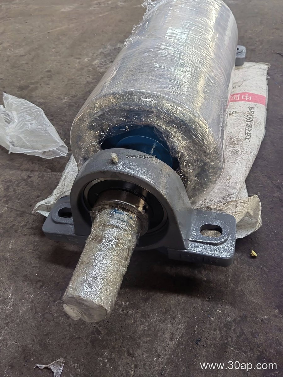
- Plain steel faces for clean, dry auxiliary paths.
- Cold vulcanized rubber lagging for standard impact mitigation.
- Hot vulcanized diamond or herringbone patterns to shed moisture and debris.
- Ceramic lagging for extreme wear zones handling heavy abrasive loads.
Common lagging thicknesses range from 8 mm to 20 mm, tailored to match the wear life requirements of the installed Heavy-Duty Conveyor Belt or specialized Port Conveyor Belt running along the line.
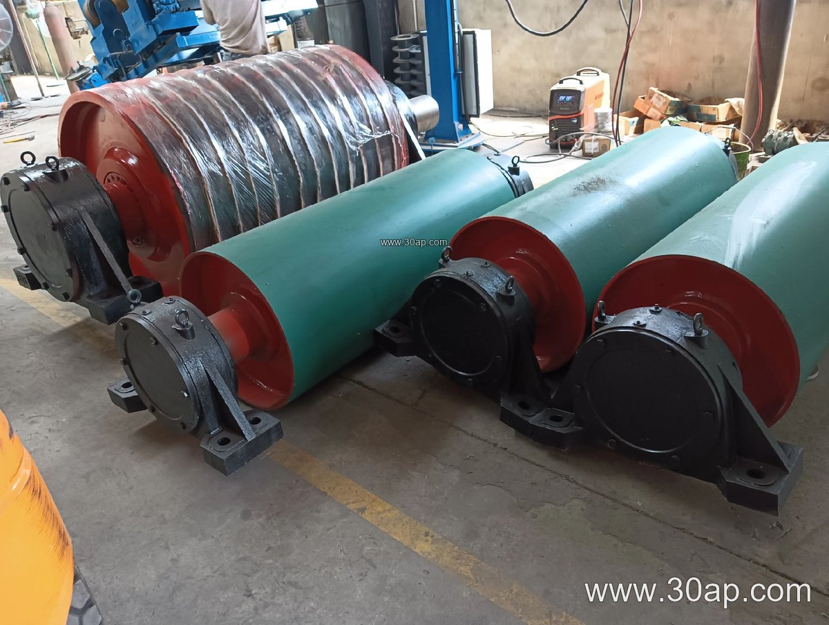
Structural Reference Data and Dimensions
Engineering specifications for a conveyor bend pulley depend on calculated belt tension, wrap angles, and spatial constraints rather than a single fixed rule. Shell widths are typically broader than the running belt width to accommodate lateral movement and guide tracking safely. Below is a reference chart showing common dimensional pairings utilized in heavy industrial design calculations:
| Nominal Belt Width | Approximate Shell Width | Representative Diameters | Common Shaft Diameters |
|---|---|---|---|
| B650 | 750 mm | Ø315, Ø400, Ø500 | Ø70, Ø80, Ø90 |
| B800 | 950 mm | Ø400, Ø500, Ø630 | Ø90, Ø100, Ø120 |
| B1000 | 1150 mm | Ø500, Ø630, Ø800 | Ø120, Ø140, Ø160 |
| B1200 | 1400 mm | Ø630, Ø800, Ø1000 | Ø140, Ø160, Ø180 |
| B1400 | 1600 mm | Ø800, Ø1000, Ø1250 | Ø160, Ø180, Ø200 |
Shaft sizing is determined strictly through torque, bending moment, and load calculations rather than relying on belt width alone. Whether the system operates with an EP Conveyor Belt or an impact-resistant core, engineers must verify that bearing selections match the operational radial and axial forces.
Maintenance and Inspection Best Practices
Routine checks ensure long service intervals for every conveyor bend pulley in service. Operators should inspect the shell surface for abnormal rubber wear, check bearing housing temperatures, and verify that the surrounding conveyor belt remains centered. Clearing fine material accumulation prevents premature lagging degradation and maintains smooth rotation across all installed idler roller paths.