Understanding the Labyrinth-Sealed Idler Design
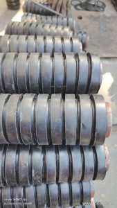
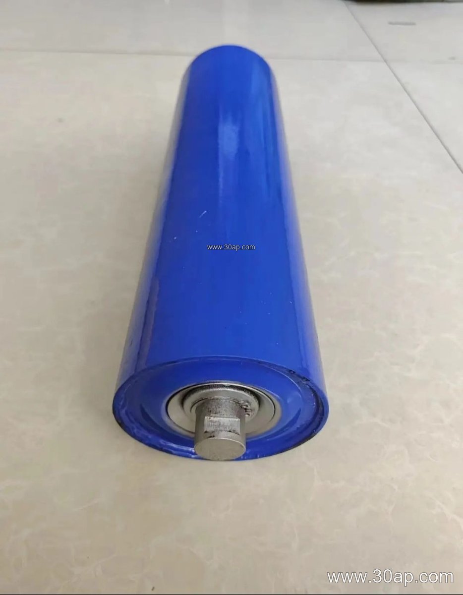
In heavy-duty material handling operations found across bustling aggregate crushing plants and large-scale bulk terminals, maintaining bearing integrity is essential for continuous performance. The Labyrinth-Sealed Idler relies on a specialized multi-stage sealing mechanism designed to block fine abrasive dust, moisture, and debris from entering the internal housing. Unlike standard contact seals, this non-contact labyrinth path creates intricate directional turns that naturally trap and expel foreign particles during rotation. When paired with a robust steel tube shell and precision bearings such as 6204, 6205, 6305, 6306, 6308, or 6310, this design significantly extends operational lifespans under demanding conditions.
Structural Components and Dimensional Variety
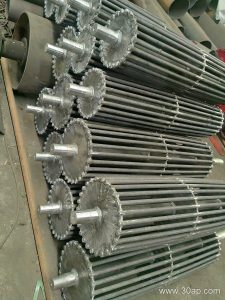
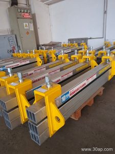
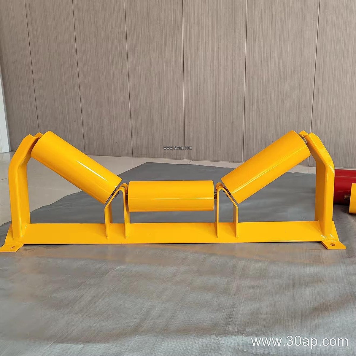
The overall construction of an idler roller involves careful pairing of shaft geometry, bearing pockets, and outer shell materials. Operators often select specific configurations based on the physical demands of their conveyor belt layout. Shell surfaces can be specified as steel pipe, nylon, ceramic, or equipped with rubber rings depending on impact and wear requirements. To provide a clearer view of common framework compatibility, typical dimensional parameters are outlined below:
- Shell Diameters: Ø89, Ø108, Ø127, Ø159, Ø194
- Standard Bandwidths: B650, B800, B1000, B1200, B1400
- Troughing Angles: 20 degree, 30 degree, 35 degree, 45 degree
- Roller Length References: B800 using 315 mm, B1000 using 380 mm, B1200 using 465 mm (variations apply for side and center rollers)
Application in Aggressive Industrial Environments
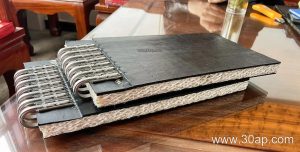
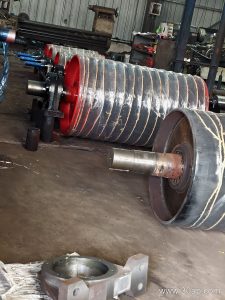
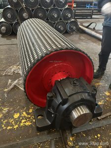
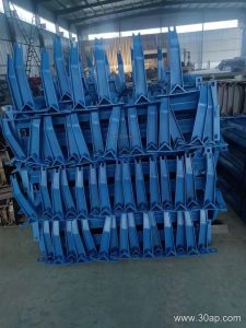
Selecting the right components ensures smooth interaction with a heavy-duty Steel Cord Conveyor Belt or an abrasion-resistant EP Conveyor Belt carrying heavy loads. In a busy aggregate crushing plant, fine rock powder and constant impact challenge every moving part. Installing a well-sealed idler along the carrier and return paths minimizes sudden seizures that could otherwise damage the rubber conveyor belt or strain the drive and tail conveyor pulley assemblies. Proper alignment with the supporting conveyor bracket also prevents uneven edge wear.
Technical Reference and Selection Guidelines
When planning maintenance or system upgrades, engineers evaluate operating speeds, ambient moisture, and material characteristics. While standard steel tube configurations handle routine bulk transfer, specialized setups prevent material buildup near the conveyor roller zones. Maintenance teams should routinely inspect rotation freedom and check for unusual acoustic signatures indicating bearing wear. By matching appropriate roller diameters to the specific conveyor belt speed and tension parameters, facilities achieve optimal load distribution across every troughing idler set.