Understanding the Mechanics of a Conveyor Belt Lagged Pulley
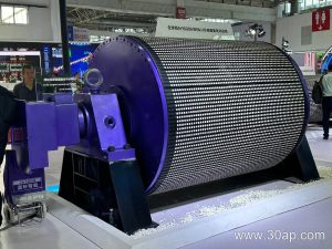
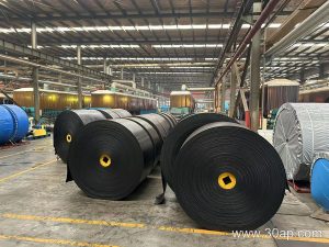
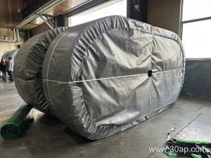
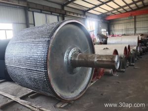
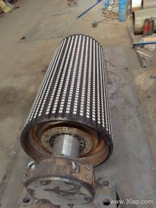
In heavy industrial processing lines, maintaining consistent frictional grip between the rotating drive components and the moving Steel Cord Conveyor Belt is essential for smooth material conveyance. A conveyor belt lagged pulley features an outer rubber or ceramic surface bonded to the steel shell, significantly increasing the coefficient of friction. This enhanced grip prevents slippage, reduces belt wear, and ensures efficient power transmission even under high-torque starting conditions.
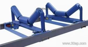
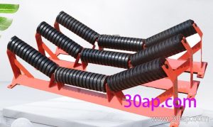
Unlike bare steel alternatives, the exterior coating absorbs impact forces from the burden and helps shed accumulated moisture or fine dust particles. When integrated alongside properly aligned idler roller assemblies and sturdy support structures, this component maintains stable line tension and predictable tracking across demanding operational cycles.
Surface Profiles and Material Options
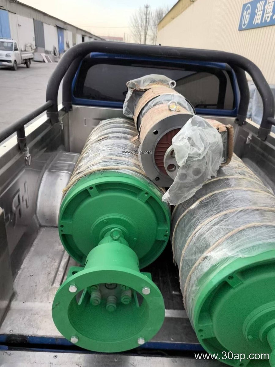
The performance of any conveyor belt lagged pulley depends heavily on its outer lagging pattern and the chosen rubber thickness. Operations handling abrasive limestone or clinker often rely on specialized Abrasion Resistant Conveyor Belt networks paired with vulcanized lagging to maximize service intervals. Surface designs vary depending on environmental moisture and drainage requirements.
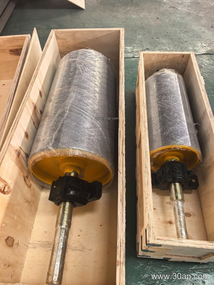
| Surface Form | Lagging Thickness (mm) | Typical Application Focus |
|---|---|---|
| Plain Rubber | 8, 10, 12 | General light-duty transfer |
| Diamond Pattern | 10, 12, 15 | Bi-directional conveying lines |
| Herringbone / Chevron | 12, 15, 20 | High-moisture or inclined wet lines |
| Ceramic Tile Lagging | 15, 20 | Extreme abrasion and high tension |
Dimensional Parameters and Sizing Reference
Specifying a conveyor belt lagged pulley requires careful evaluation of belt widths, shell diameters, and shaft loads. Designers usually match shell dimensions to the physical layout of the conveyor frame and the rated tension of the line. The shell width is normally manufactured slightly wider than the corresponding fabric or steel cord carcass to ensure complete edge coverage.
| Belt Width (B) | Nominal Shell Width (mm) | Common Diameter Options (mm) |
|---|---|---|
| B650 | 750 | Ø400, Ø500, Ø630 |
| B800 | 950 | Ø500, Ø630, Ø800 |
| B1000 | 1150 | Ø630, Ø800, Ø1000 |
| B1200 | 1400 | Ø800, Ø1000, Ø1250 |
| B1400 | 1600 | Ø1000, Ø1250, Ø1400 |
Shaft dimensions such as Ø90, Ø100, Ø120, Ø140, or Ø160 mm are determined strictly by analyzing the torque output and radial loads rather than relying on a fixed ratio tied solely to the belt width. Proper selection ensures the entire assembly withstands continuous operational stresses in demanding cement plant and aggregate handling environments.