What a 1000mm Diameter Conveyor Pulley Is
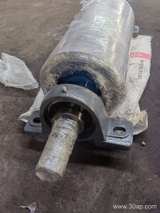
A 1000mm diameter conveyor pulley is a large-drum component used where belt tension, torque and material load run high. In the trade it is often called a Ø1000 pulley or a 1 m drum pulley. It is a single product family, not a substitute label for other positions on the conveyor: a drive pulley, tail pulley and bend pulley each do a different job, and a Ø1000 unit may serve any of these roles only when the design calls for it.
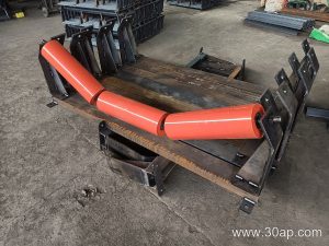
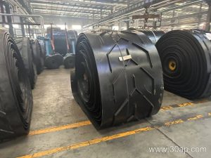
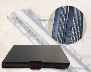
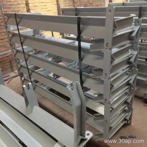
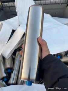
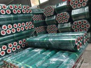
Such a drum usually appears on wide, heavy-duty belts. It pairs naturally with a Steel Cord Conveyor Belt or a high-strength fabric belt on main haulage lines, and it is common to see it working alongside conveyor idler roller strings and sturdy conveyor bracket frames.
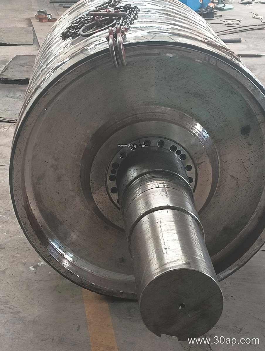
How the Drum Is Built
The shell is normally a rolled steel cylinder, machined and balanced, with end discs welded to the hub. The shaft is sized by torque and radial load, not by belt width alone, so a Ø1000 drum may carry shafts in the Ø120 to Ø200 range or larger depending on the duty. Common shell face widths sit a little wider than the belt, for example about 1150 mm for a B1000 belt or around 1400 mm for a B1200 belt. These are typical references, not fixed pairings.
Surface finish is a major choice. Plain, cast rubber, cold-bonded rubber, hot-vulcanized rubber, diamond grooving, chevron grooving and ceramic lagging are all used, with lagging thickness commonly 8, 10, 12, 15 or 20 mm. On a large drum the lagging protects the belt and improves grip, which matters when a Heat Resistant Conveyor Belt or an abrasive ore belt runs at high tension.
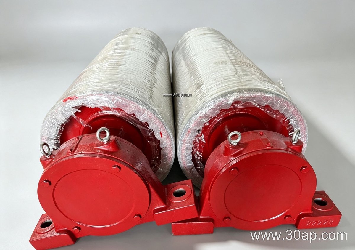
Where It Fits in the Plant
Large drums are typical in a limestone quarry, an iron ore transfer station, a coal preparation plant or a power plant coal yard. They also turn up in cement clinker lines and port bulk terminals. In these places the pulley is expected to survive dust, grit and continuous load, so the mating belt is often an Abrasion Resistant Conveyor Belt or a heavy fabric-core grade.
Position matters. A drive pulley transmits power and needs good lagging contact. A tail pulley guides the return side and may be plainer. A bend pulley changes belt direction and is usually smaller, so a Ø1000 bend pulley is only chosen when the route and belt stiffness require it. A 1000mm diameter tail or drive drum is not interchangeable with a bend drum in the same layout without a design check.
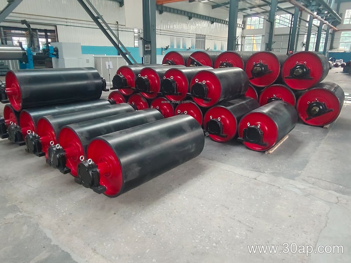
Reference Dimensions and Surface Options
The table below gives common reference values. Actual supply is confirmed by the pulley drawing and load calculation.
| Item | Common reference values |
|---|---|
| Drum diameter | Ø1000 mm |
| Belt width examples | B800, B1000, B1200, B1400, B1600 |
| Shell face width examples | about 950, 1150, 1400, 1600, 1800 mm |
| Lagging thickness | 8, 10, 12, 15, 20 mm |
| Surface forms | plain, cast rubber, cold-bonded, hot-vulcanized, diamond, chevron, ceramic, flat rubber |
| Shaft diameter range | Ø120 to Ø200 mm and above, by torque and load |
| Typical positions | drive, head, tail, tension, take-up, bend |
Typical combinations such as B1200 × Ø1000 or B1400 × Ø1000 are seen in practice, but no belt width is locked to one diameter. A B1000 belt can run on a smaller drum in a light duty line, and a wide belt may need a larger drum to limit bending stress.
Buyer Checklist
- Confirm the pulley position first: drive, tail, bend, tension or snub. Each has different loading.
- Provide belt width, belt type and belt tension. A Flame Retardant Conveyor Belt in an underground coal mine may need different lagging and clearance than a quarry belt.
- State the lagging form and thickness, and whether grooving or ceramic tiles are required.
- Give the shaft diameter from the drive calculation, not from a rule of thumb based on width.
- Check bearing size, hub style and mounting space against the conveyor pulley drawing and the bracket interface.
- Ask for balance grade, weld inspection and runout data where the drum is large and fast.
A 1000mm diameter conveyor pulley is a serious piece of rotating equipment. Matching it to the belt, the load and the mounting point is more important than picking a number from a table. Use the reference figures as a starting point, then let the actual duty decide the final shaft, lagging and shell width.