What a Galvanized Conveyor Bracket Does on a Belt Line
A galvanized conveyor bracket is the steel support that holds idler rollers at the correct height, angle, and spacing along a conveyor frame. It is the interface between the structure and the rotating parts: the bracket carries the load path from the belt and material into the stringers, while allowing the rollers to turn freely. Because the part sits close to dust, moisture, and washdown, hot-dip or pre-galvanized coating is often chosen to slow corrosion in quarries, coal handling plants, and port terminals.
In practice, the bracket is a fabricated assembly rather than a single plate. Angle steel, channel steel, or folded plate is cut, punched, and welded into a frame that matches the belt width and the trough profile. Slots and bolt holes are positioned so the roller shafts drop in and lock without shimming on site.
Construction and Surface Treatment
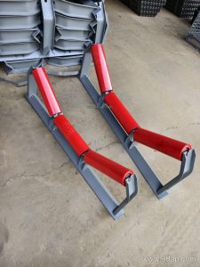
Most units combine a cross member with two or three roller seats. The cross member spans the conveyor stringers, and the seats are set at the trough angle. Fabrication details matter more than they appear: weld spatter left inside a roller seat can stop a shaft from seating, and sharp edges can cut into the coating during transport.
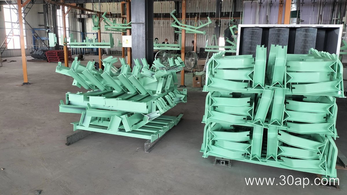
- Material: angle steel, channel steel, or folded steel plate
- Coating: hot-dip galvanized after fabrication, or pre-galvanized sheet with touched-up welds
- Fixing: bolted to the frame through slotted holes, or welded where the design allows
- Roller seats: fixed, adjustable, or pre-set to one trough angle
Galvanizing is not a substitute for correct drainage. Brackets that trap water and fines will still corrode at the coating cut edges, so weep gaps and open profiles help. On a Mining Conveyor Belt line carrying wet ore, this detail often decides how long the support lasts.
Common Configurations
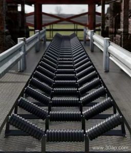
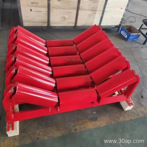
The bracket family covers carry-side and return-side positions. A trough bracket holds three rollers and sets the trough angle; a transition bracket near the pulley changes the angle gradually so the belt is not forced to fold sharply. Return brackets are usually flatter, and V-return designs help center the belt on the way back.
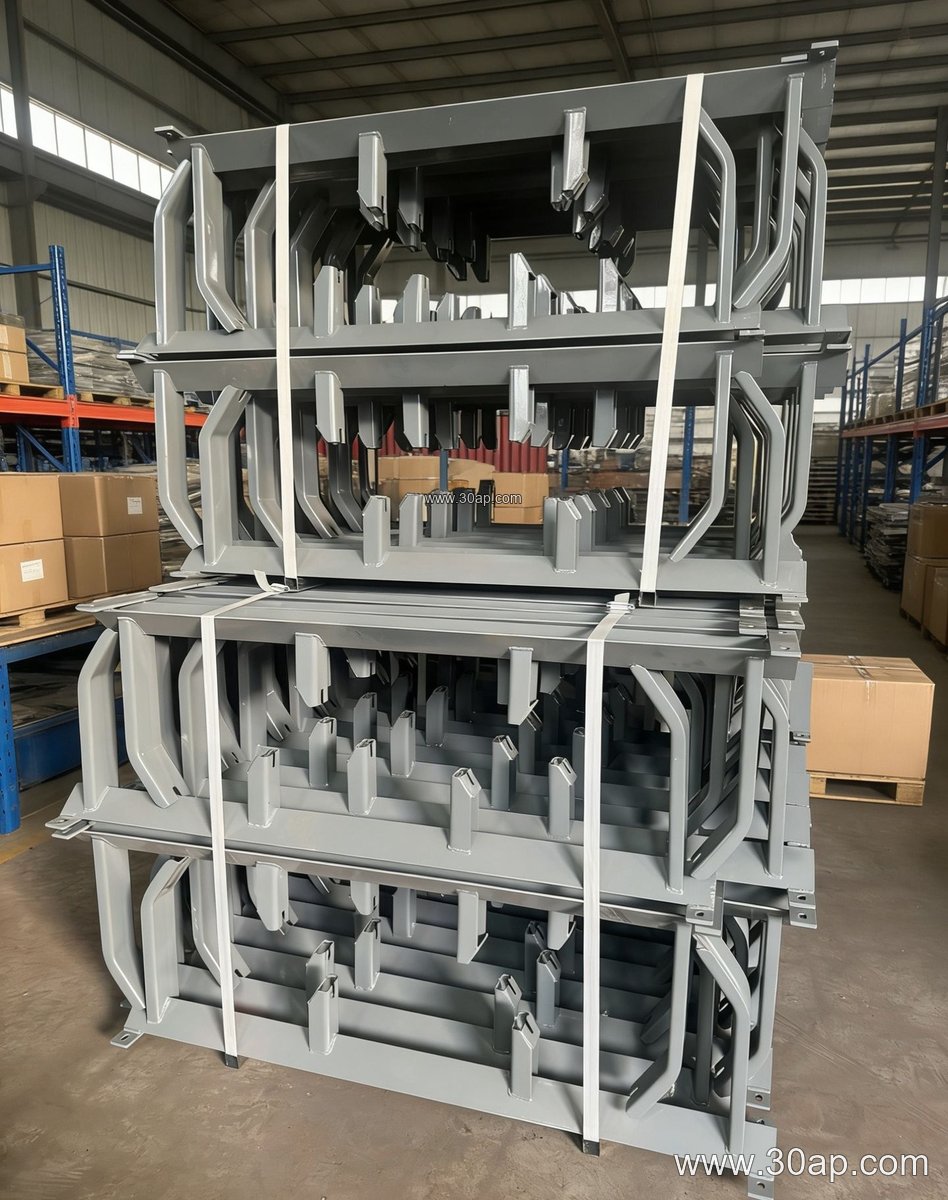
| Configuration | Typical position | Notes |
|---|---|---|
| Trough bracket | Carry side | Usually 20°, 30°, 35°, or 45° trough angle |
| Transition bracket | Near head or tail pulley | Steps the trough angle down toward the pulley |
| Return bracket | Return side | Flat or V-shaped support for the empty belt |
| Impact bracket | Load point | Carries cushion rollers under the chute |
| Adjustable bracket | Carry side | Trough angle set on site within a range |
Fixed and adjustable versions are not interchangeable in every case. An adjustable bracket simplifies alignment when a conveyor is commissioned or when the belt is replaced, while a fixed bracket gives a stiffer, more predictable roller position once the profile is settled.
Matching Belt Width, Trough Angle, and Roller Diameter
Bracket dimensions follow the belt width and the roller diameter, but there is no single correct pairing. A B800 frame may run 30° or 35° with Ø108 rollers depending on material surcharge and belt speed, while a B1200 line in a cement plant might use 35° or 45° with Ø133 rollers. Cross member length, hole spacing, and mounting height are set by the conveyor design, not by a catalogue rule.
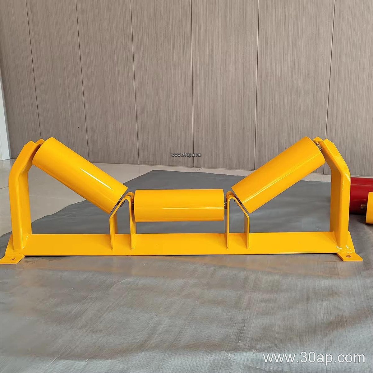
| Belt width | Common trough angle | Common roller diameter |
|---|---|---|
| B500 | 20°–30° | Ø89 |
| B650 | 30° | Ø89–Ø108 |
| B800 | 30°–35° | Ø108 |
| B1000 | 35° | Ø108–Ø133 |
| B1200 | 35°–45° | Ø133 |
| B1400 | 35°–45° | Ø133–Ø159 |
| B1600 | 35°–45° | Ø159 |
| B1800–B2000 | 35°–45° | Ø159–Ø194 |
These values are common references, not fixed rules. Confirm the shaft diameter, seat width, and bolt pattern against the actual roller and frame drawings before ordering. A Steel Cord Conveyor Belt on a long overland run usually needs a stiffer bracket than a short fabric line at the same width.
Where These Brackets Are Used
You will find them in coal preparation plants, limestone quarries, and aggregate crushing and screening lines, where dust and wet fines attack bare steel quickly. They are also common in power plant coal yards and port ship-loading systems, where salt air adds to the corrosion load. A galvanized surface is a practical default in these environments, though it should be specified with the right coating thickness for the site.
At a crusher discharge, an impact bracket under the chute protects the belt from lump size and drop height. Further along the same line, standard trough brackets support the loaded belt, and return brackets keep the empty side tracking. In a tunnel spoil line or a fertilizer plant, the same logic applies with different corrosion and cleaning demands.
Buyer Checklist
- Belt width and trough angle, confirmed against the frame drawing
- Roller diameter and shaft end type, so the seat fits without modification
- Fixed or adjustable design, and the range of angle adjustment
- Coating method and thickness, plus treatment of weld areas
- Mounting hole spacing and cross member length
- Load point position, if cushion or impact rollers are needed
- Compatibility with the conveyor pulley layout near transitions
Order brackets together with the idler roller and belt specification so the seat dimensions, angle, and coating are checked as one system. A small mismatch at the seat is easy to fix at the drawing stage and expensive to fix on a stopped conveyor.