What the Conveyor Carrying Bracket Does
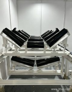
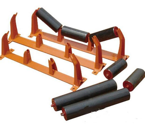
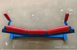
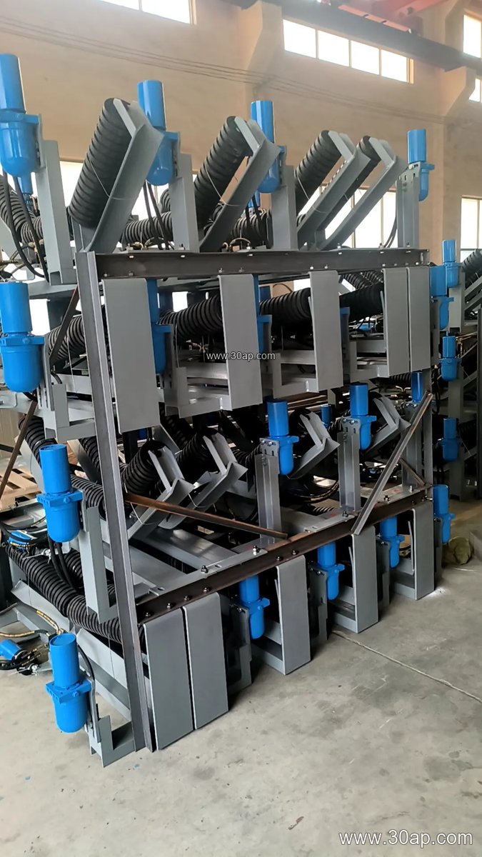
A conveyor carrying bracket is the steel frame that holds the idler rollers in place along the load-bearing side of a belt conveyor. In everyday plant language it is often shortened to carrying bracket or simply bracket, while the same part family also includes return brackets on the empty strand. The bracket does not move material itself; its job is to keep each idler at the right height, spacing and trough angle so the belt keeps a stable profile from the loading point to the discharge pulley.
Because the belt rests on the rollers, the bracket quietly controls how evenly the load is distributed. On a quarry conveyor or a cement plant transfer line, a weak or misaligned bracket shows up quickly as belt wander, spillage and uneven roller wear. That is why buyers usually treat the bracket as a structural component rather than a minor accessory.
Construction and Common Forms
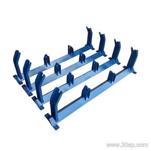
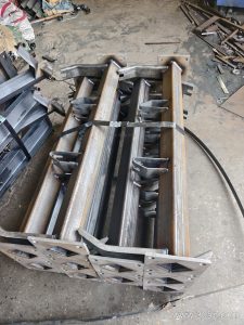
Most brackets are fabricated from angle steel, channel steel or folded steel plate, then drilled for idler shafts and bolted to the conveyor stringer. Welded or bolted designs both exist. The main variants follow the shape of the belt they support:
- Trough carrying bracket for the loaded strand, normally set at 20, 30, 35 or 45 degrees.
- Transition bracket near the tail pulley, where the belt changes from flat to troughed.
- Return bracket, including the V-shaped return form, for the empty side.
- Impact bracket under the loading chute, often paired with cushion rollers.
- Self-aligning and forward-leaning brackets for belt tracking.
- Adjustable bracket, which allows the trough angle to be changed within a range.
Forward-leaning brackets are usually set at about 1.5 to 2 degrees to help centre the belt. Adjustable designs are useful where the same conveyor handles different materials and the operator wants to fine-tune the trough profile.
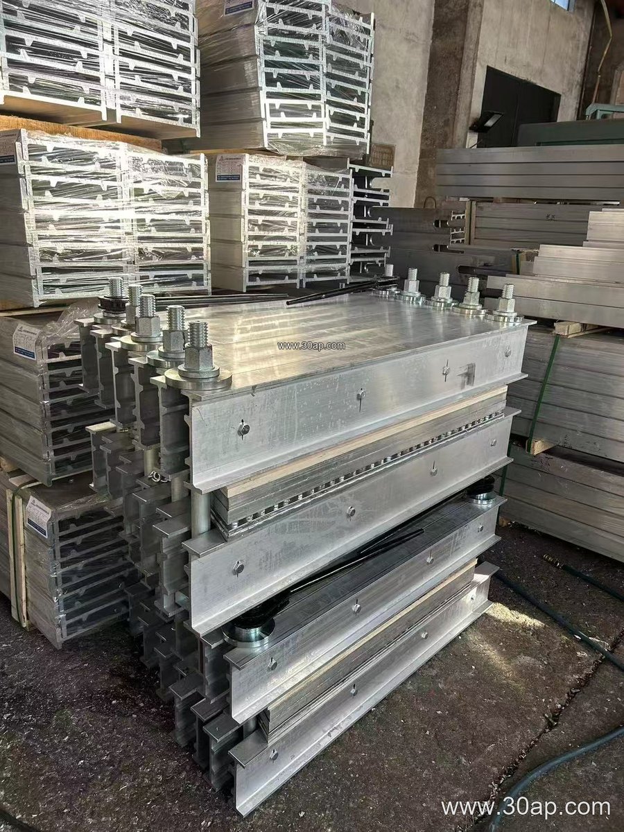
Matching Bracket, Belt Width and Roller Diameter
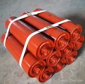
Bracket dimensions follow the belt width and the roller diameter, not the other way round. A B800 frame with a 35 degree trough and Ø108 rollers is a common combination, and a B1200 frame at 45 degrees with Ø133 rollers is equally normal. Smaller lines such as B650 at 30 degrees with Ø89 rollers also appear in aggregate and sand plants. None of these pairings is a rule: the same belt width can be built with different trough angles and roller diameters depending on load, speed and material lump size.
Installation hole spacing and crossbeam length change with belt width and trough angle, so these should be confirmed against the conveyor drawing rather than assumed. Reference values below are typical ranges only.
| Belt width | Typical trough angle | Typical roller diameter |
|---|---|---|
| B500 – B650 | 20 – 30 degrees | Ø89 – Ø108 |
| B800 – B1000 | 30 – 35 degrees | Ø108 – Ø133 |
| B1200 – B1400 | 35 – 45 degrees | Ø133 – Ø159 |
| B1600 – B2000 | 35 – 45 degrees | Ø159 – Ø194 |
Where These Brackets Are Used
In a coal washing plant, carrying brackets support the loaded strand through wet, dusty conditions, so galvanised or well-painted steel is often preferred. In an iron ore or limestone crushing circuit, impact brackets take the shock at the transfer point before the material settles into a steady trough. Power plant coal handling and port ship-loading conveyors use long runs of matched brackets to keep the belt line straight and reduce tracking corrections.
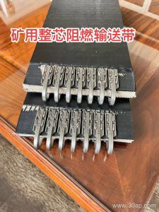
The bracket has to work with the rest of the system. A heavy-duty steel cord conveyor belt needs stiffer frames and larger rollers than a lighter fabric construction, and a flame retardant belt in an underground mine still relies on correctly spaced brackets to avoid rubbing. Equally, an abrasion resistant belt will last longer when the trough angle matches the material and the rollers turn freely.
Buyer Checklist
Before ordering, confirm the belt width, the required trough angle, the roller diameter and the mounting hole pattern. State whether the frame is fixed or adjustable, and whether it is for the carrying side, the return side or a transition zone. Check the steel section and surface treatment against the site environment, and ask for the crossbeam length to be tied to your conveyor drawing.
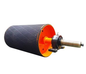
During installation, keep brackets square to the belt centreline and at a consistent height; a single high or low frame can start a tracking problem that looks like a roller fault. Spare brackets in the most common sizes help reduce downtime in a busy sand or cement line. For related components such as the idler roller and the conveyor pulley, match the bracket specification to the same duty level so the whole conveyor frame works as one system.