What a Conveyor Take-Up Pulley Does
A conveyor take-up pulley is the drum that keeps a conveyor belt under controlled tension. It usually sits at the tail end or in a dedicated take-up section of the conveyor frame, and it moves along a guided track or slide as the belt stretches or contracts. Without this movement, a loose belt would slip on the drive pulley, wander off the idler roller, and spill material at transfer points. The take-up pulley is therefore a tensioning drum, not a drive drum and not a bend pulley; those roles belong to other positions in the conveyor.
The same component is also called a tension pulley or take-up drum in many plant drawings. Whatever the name, its job is to hold the return side of the conveyor belt at a working tension that suits the load, the belt length, and the starting conditions.
How the Take-Up Pulley Is Built
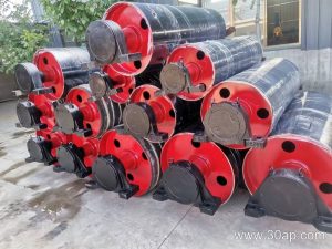
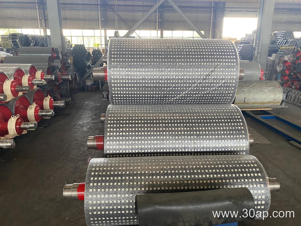
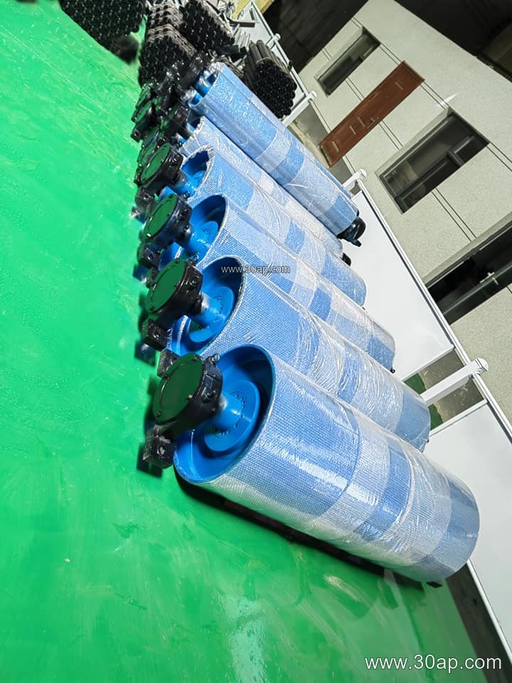
A typical unit combines a steel shell, a shaft, bearing housings, and a surface treatment. The shell is machined and balanced, and the shaft is sized by torque and load rather than by belt width alone. Common shaft diameters include Ø60, Ø80, Ø100, Ø120, and Ø140, but a Ø120 shaft is not automatically correct for a given belt. Bearing selection, frame design, and travel distance all matter.
The drum surface may be plain or covered. Rubber lagging, diamond-pattern lagging, and ceramic lagging are used where grip and wear resistance help. Lagging thickness is often 8, 10, 12, 15, or 20 mm. In a dusty coal preparation plant or a limestone quarry, the lagging choice affects how well the belt tracks during tension changes.
Common Sizes and Position in the Frame
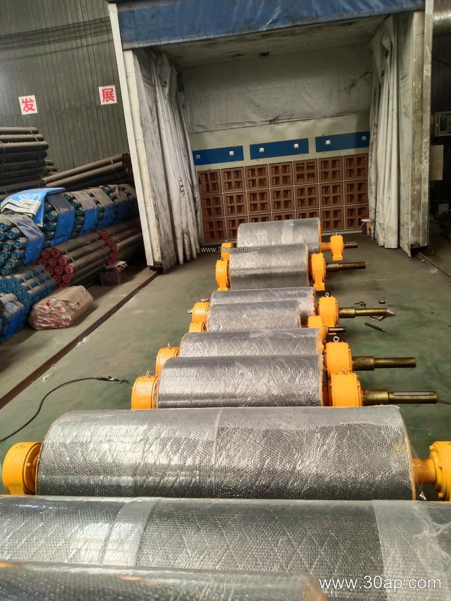
Take-up drums are matched to the belt and to the frame layout. Face width is usually a little wider than the belt, for example about 600 mm for B500, about 950 mm for B800, and about 1400 mm for B1200. Diameter choices range from Ø250 and Ø315 up to Ø800, Ø1000, or larger, depending on belt speed and bend requirements. A B800 × Ø500 unit and a B1200 × Ø1000 unit are both plausible combinations, but neither is a fixed rule.
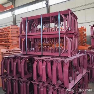
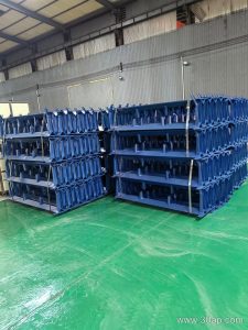
The drum is mounted in a conveyor bracket or slide assembly that allows horizontal or vertical travel. Gravity take-up towers, screw take-up frames, and hydraulic tensioning systems are common arrangements. The travel length should be enough to cover belt elongation over the operating cycle, with spare stroke for re-splicing.
Where It Appears in Bulk Handling
You will find a tension drum on long overland conveyors at a sand and gravel pit, on coal yard belts at a power plant, and on clinker transport lines in a cement works. It also appears in crushing and screening circuits, port bulk terminals, and tunnel spoil removal. In each case the take-up pulley works together with the conveyor belt, the carrying idler roller, and the return rollers to keep the belt centered and stable.
Position matters. A take-up drum at the tail keeps tension on the return run before the belt reaches the drive. A take-up unit mounted near the drive can shorten the tensioned span. Neither arrangement replaces a tail pulley or a bend pulley; it adds tension control to the layout.
What Buyers Should Check
- Belt width and face width: confirm the drum face suits the belt, not just the nominal width.
- Diameter and lagging: check the bend radius and the grip needed for the application.
- Shaft and bearings: verify load ratings against the actual tension, not a guessed value.
- Travel and adjustment: confirm the slide or bracket gives enough stroke for belt stretch.
- Surface protection: choose lagging and coating for dust, moisture, and abrasive material.
Ask for a drawing that shows the shell, shaft, bearing centers, and lagging thickness. A take-up pulley that fits the frame but not the tension range will cause tracking problems and premature belt wear. When the drum is specified with the conveyor belt, idler roller, and conveyor bracket as one system, the tensioning behavior is easier to predict and maintain.