What a Tail Bend Pulley Does
A tail bend pulley is a conveyor pulley mounted near the tail end of a belt conveyor, where it guides the returning belt into the tail pulley or redirects it toward a take-up arrangement. In many layouts it works together with the tail pulley to form the belt loop, so the belt leaves the carrying side, wraps the tail pulley, and then passes over the bend pulley before heading back along the return strand. Because it changes belt direction rather than driving the belt, it belongs to the redirecting family of conveyor pulleys, not to the drive or head end.
The distinction matters when specifying spare parts. A drive pulley transmits torque through a lagged shell and a locked shaft connection, while a tail pulley at the loading end supports the belt and often carries a wing or self-cleaning profile. A bend pulley may look similar in shape but has a different duty, and in most cases a bend pulley cannot be swapped for a drive or tail pulley without a review of the whole conveyor layout.
Construction and Surface Options
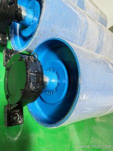
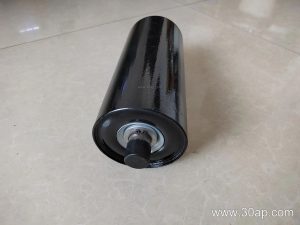
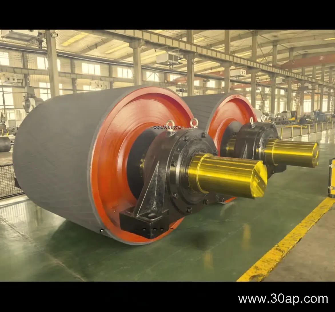
Most tail bend pulleys use a welded steel shell with end discs and a through shaft, supported by bearing housings that bolt to the conveyor bracket or tension frame. Shell diameter and face width follow the belt width and the allowable bending radius of the belt, and the shaft diameter is set by torque and radial load rather than by belt width alone. Common shaft sizes include Ø80, Ø100, Ø120 and Ø140, but the final value should come from the conveyor designer.
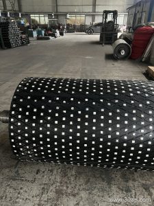
Surface treatment depends on whether the pulley needs friction or cleaning. Plain finish suits light contact and simple return runs. Rubber lagging in 8, 10 or 12 mm is common where belt tracking and wear protection matter, and diamond or herringbone patterns help shed water and fines. Ceramic lagging is chosen in wet or abrasive service such as a coal preparation plant or a limestone quarry. A tail bend pulley usually runs on the slack side, so heavy drive-level lagging is not always necessary, but a worn or polished shell can cause belt slip and misalignment.
Typical Reference Combinations
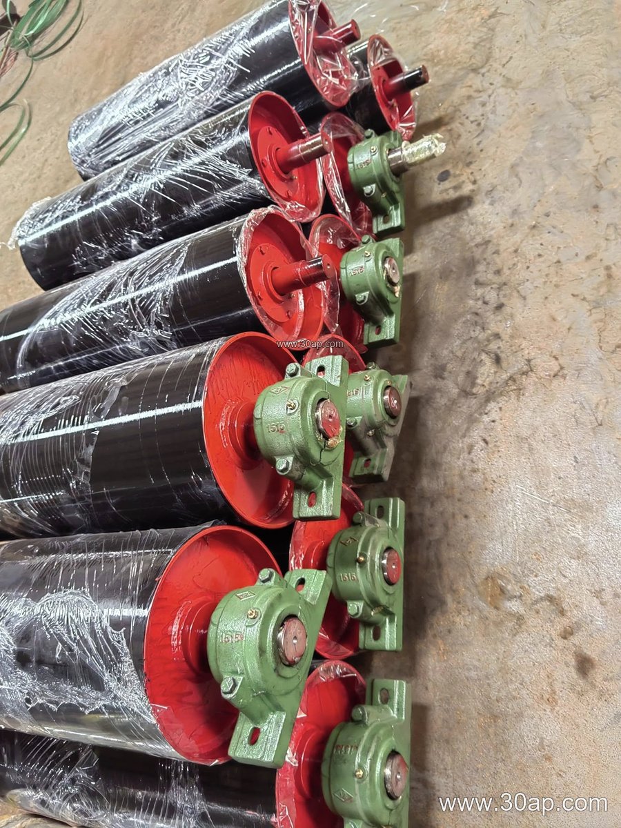
The table below lists common reference pairings between belt width, pulley face width and shell diameter. These are examples for discussion, not fixed rules, and the final selection is made from belt tension, wrap angle and shaft load.
- B650 belt: face width about 750 mm, shell Ø315 to Ø400
- B800 belt: face width about 950 mm, shell Ø400 to Ø500
- B1000 belt: face width about 1150 mm, shell Ø500 to Ø630
- B1200 belt: face width about 1400 mm, shell Ø630 to Ø800
- B1400 belt: face width about 1600 mm, shell Ø800 to Ø1000
- B1600 belt: face width about 1800 mm, shell Ø800 to Ø1250
Larger diameters such as Ø1250, Ø1400 and Ø1600 appear on high-tension or long overland conveyors, where a bigger bend radius reduces belt stress. A small aggregate line may use B500 with a Ø250 or Ø320 shell, while a power plant coal handling system might run B1400 with a Ø1000 shell. The pairing should follow the belt manufacturer’s minimum pulley diameter, not a catalog shortcut.
Where It Fits in the Plant
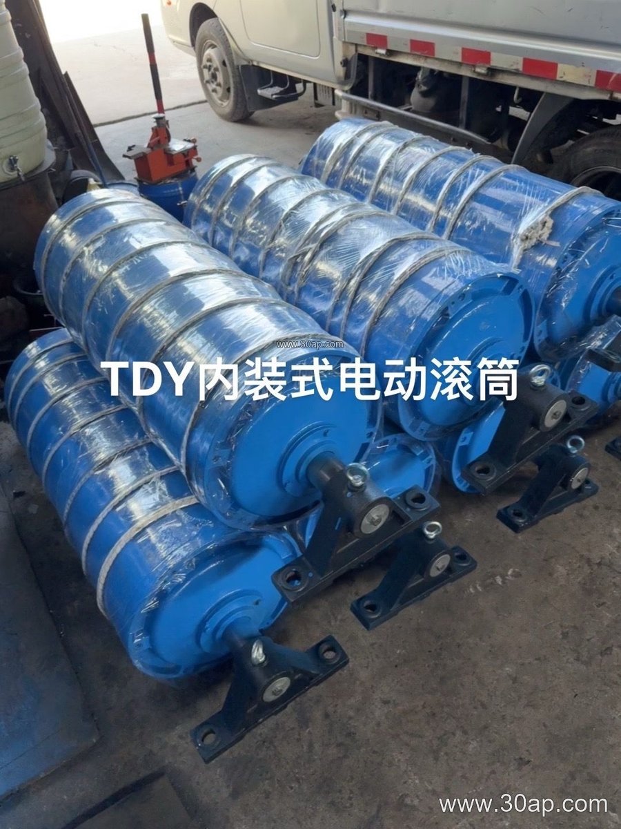
Tail bend pulleys appear in crushing and screening circuits, cement clinker transport, coal yards, iron and copper concentrators, and port bulk terminals. In a stone quarry, they often sit under the discharge chute where space is tight, redirecting the belt toward a gravity take-up. In a tunnel spoil line or a fertilizer warehouse, they may be mounted on a sliding frame so belt tension can be adjusted without moving the tail pulley itself.
The pulley should be checked against the conveyor belt path. If the bend angle is large, the belt may need a larger shell or an additional idler roller to keep contact smooth. A worn conveyor bracket or a seized bearing will show up as belt edge wear, tracking drift or a hot bearing housing, so alignment and lubrication belong in the routine inspection list.
Buyer Checklist
When ordering a tail bend pulley, confirm the belt width, the required face width, the shell diameter and the shaft diameter, plus the bearing type and mounting centers. State the lagging type and thickness if slip or abrasion is a concern, and specify whether the pulley is fixed or part of a tension frame. Ask for the drawing before production, and check that the shaft finish and keyway match the coupling or bearing housing. A clear drawing review avoids the common mistake of matching a pulley to a belt width while ignoring the actual belt tension and wrap angle.