What a Conveyor Idler Bracket Does on a Belt Conveyor
A conveyor idler bracket is the structural component that holds the idler roller in position and sets the shape of the conveyor belt at the load-carrying or return side. In practice, this part is often called a conveyor bracket or idler frame, and it is the interface between the rotating idler and the stationary conveyor structure. Its geometry decides the trough angle, the spacing between rollers, and how evenly the belt is supported from the loading point to the discharge end.
In a quarry, a coal washing plant, or a cement plant, the bracket carries the weight of the belt and the material, absorbs vibration, and keeps the idler aligned so that the belt tracks without edge damage. The choice of bracket type and material has a direct effect on belt life, power consumption, and maintenance intervals.
Construction and Common Materials
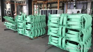
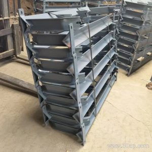
Most idler brackets are fabricated from angle steel, channel steel, or folded steel plate. The frame is drilled or punched with mounting slots for the idler shaft, and the ends are shaped to fit the conveyor stringer. A powder-coated or galvanized finish is common where moisture or dust is present.
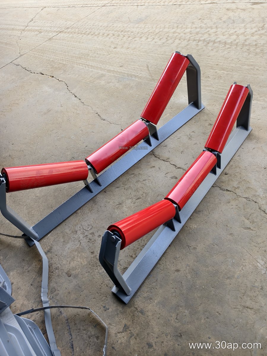
The main structural forms include:
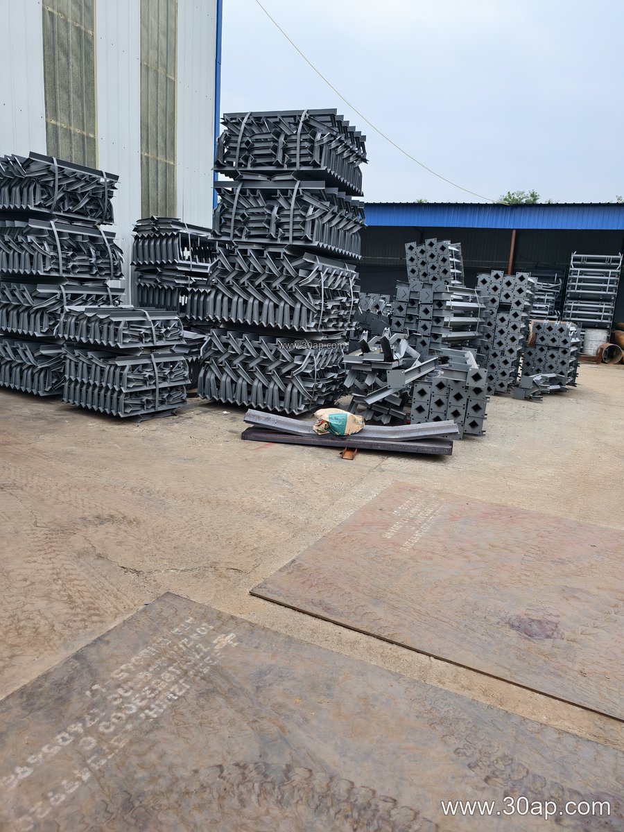
- Troughing bracket for the carrying side, with two or three idler positions
- Transition bracket near the head and tail to change the belt from flat to troughed
- Return bracket and V-return bracket for the empty strand
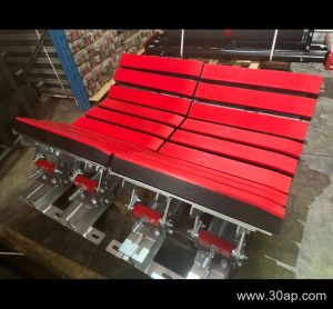
- Impact bracket with resilient mounting for the loading zone
- Self-aligning bracket that pivots to correct belt wander
- Adjustable bracket that allows the trough angle to be changed on site
Matching Trough Angle, Belt Width, and Roller Diameter
The bracket geometry is usually defined by belt width, trough angle, and roller diameter. Typical belt widths run from B500 to B2200, and common trough angles are 20, 30, 35, and 45 degrees. Roller diameters such as Ø89, Ø108, Ø133, Ø159, and Ø194 are selected according to load and belt speed. A bracket for B800 at 35 degrees with Ø108 rollers is a familiar combination, while B1200 at 45 degrees with Ø133 rollers suits heavier material. These are reference combinations, not fixed rules: a given belt width can work with more than one trough angle or roller diameter, and the final choice should follow the conveyor design.
Mounting hole spacing and crossbeam length change with belt width and trough angle, so they should be confirmed against the actual conveyor drawing rather than assumed from a single value.
Where the Bracket Fits in the Conveyor Line
On the carrying side, troughing brackets are spaced along the stringers to support the loaded conveyor belt. At the head and tail, transition brackets gradually open the belt from the trough shape, which reduces stress at the pulley. On the return side, flat and V-return brackets support the belt before it reaches the tail pulley. Impact brackets sit under the loading chute in a crusher or screening station, where falling material would otherwise damage standard rollers.
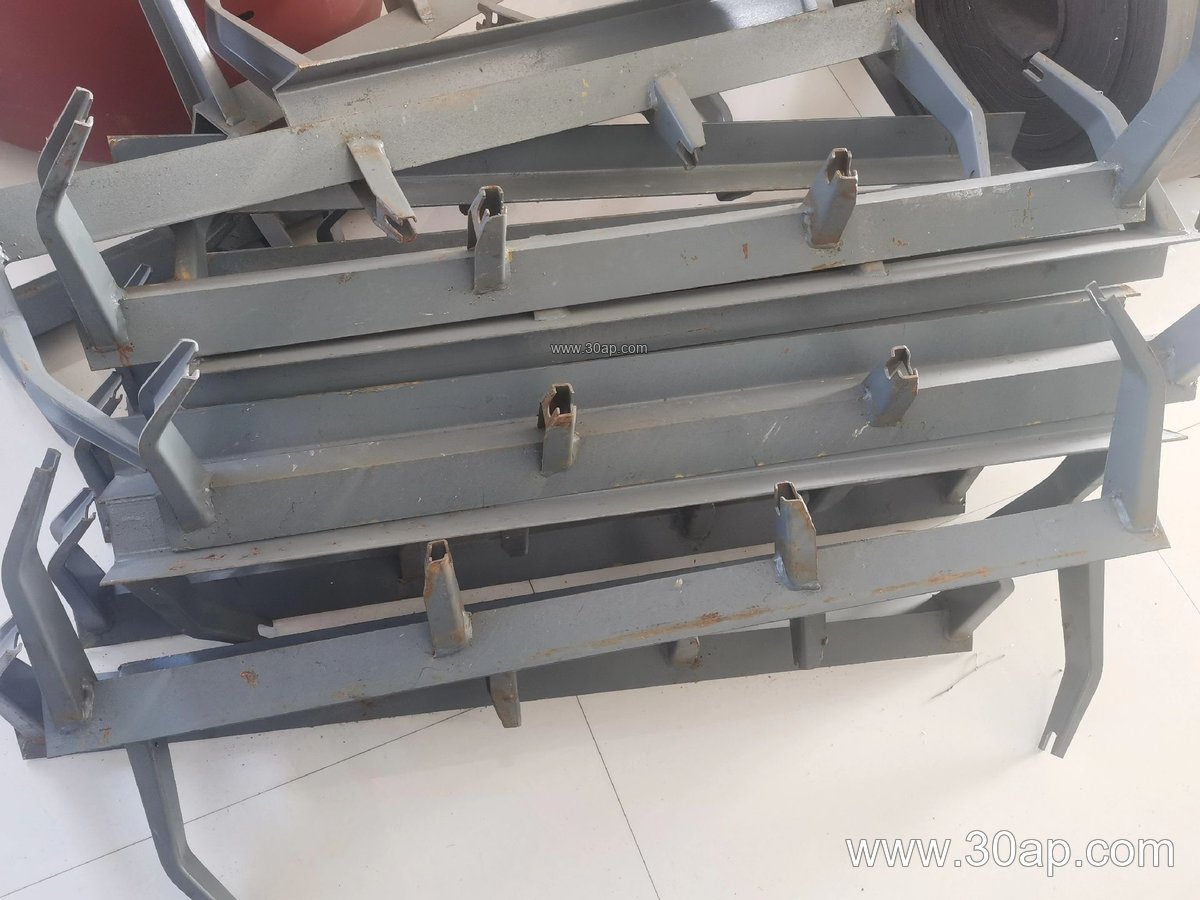
Self-aligning and forward-tilted brackets are used where belt tracking is a concern, for example on long overland runs at a port or in a tunnel spoil line. They are not a replacement for a bend pulley or a drive pulley; those components handle tension and power transmission, while the bracket only supports and shapes the belt.
Buyer Checklist
Before ordering, confirm the belt width, the required trough angle, and the idler roller diameter. Check whether the bracket must be fixed or adjustable, and whether the mounting holes match the existing stringer. Ask for the material and surface treatment, and specify the environment: coal dust, cement powder, or salt air at a port all call for different finishes.
Finally, review the installation position and the number of brackets per span. Correct spacing and a bracket that matches the conveyor frame will keep the belt running straight and extend the service life of both the idler roller and the conveyor belt.