What a Conveyor Belt Guide Idler Does on the Line
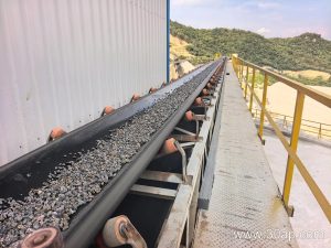
On a quarry or cement plant conveyor, the belt rarely runs perfectly centred on its own. A conveyor belt guide idler is the component that helps correct lateral drift while still carrying the load. It is not a drive pulley, not a tail pulley, and not a bend pulley. Those are different assemblies with different jobs. The guide idler belongs to the idler family, often alongside a standard carrying idler roller or a return idler roller, but its focus is belt tracking rather than pure support.
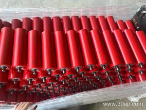
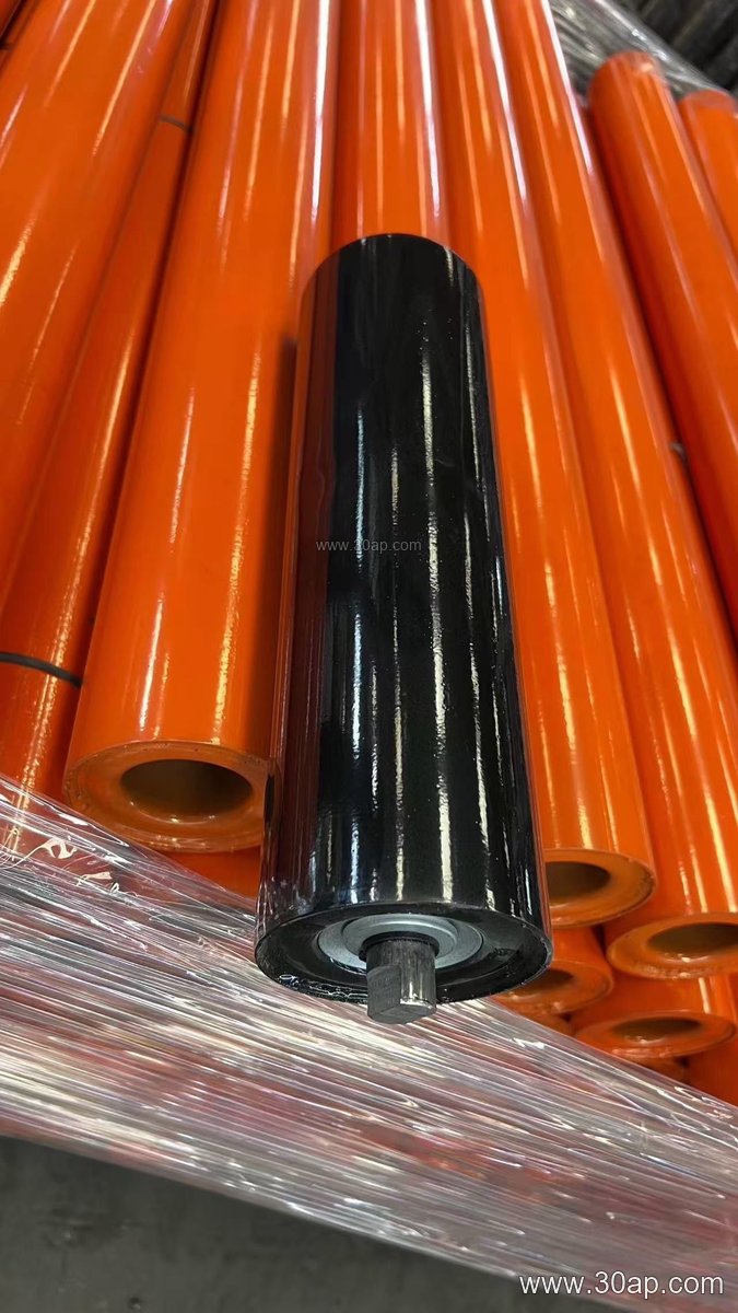
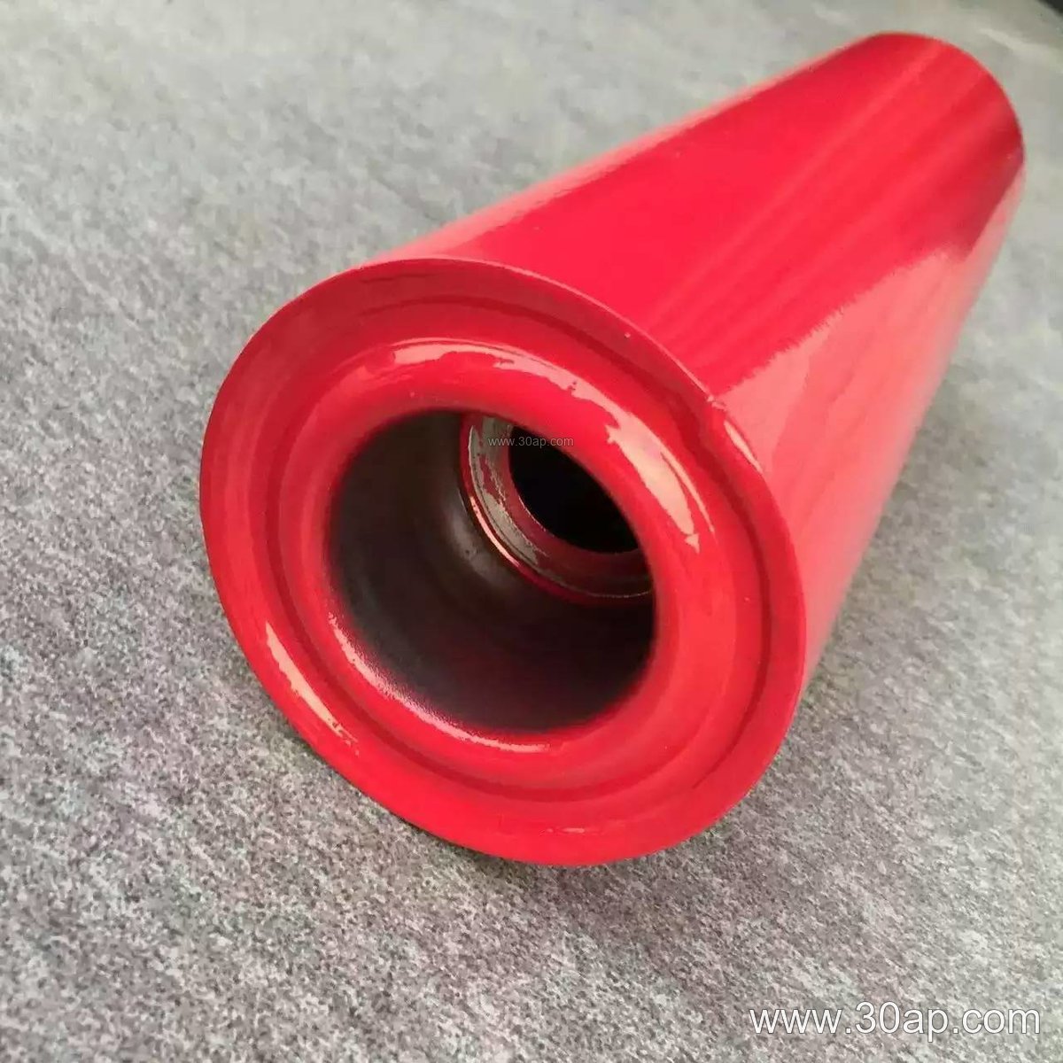
In practice, a guide idler can appear as a tapered roller, a spiral roller, or a vertical edge roller mounted near the belt edge. Some designs use a rubber-covered surface to improve grip on the belt edge. Others use a plain steel tube. The common goal is to nudge the belt back toward the centre line before misalignment becomes severe.
How It Is Built and Where It Fits
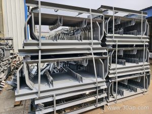
A typical guide idler uses a steel tube body, a shaft, and bearing housings. Common roller diameters include Ø63, Ø89, Ø108, Ø133, and Ø159, though the exact size depends on belt width and load. Bearings such as 6204, 6205, 6305, or 6306 are often used, but one bearing number is not locked to one roller diameter. The roller surface may be plain steel, nylon, ceramic, or rubber. The shaft ends sit in a conveyor bracket or frame that allows angular adjustment.
Position matters. A guide idler is often installed on the carrying side just ahead of a problem zone, or on the return side where the belt tends to wander. It may work together with a self-aligning idler, but it is not a replacement for a training idler. The two can complement each other: the guide idler reacts at the edge, while a friction self-aligning idler reacts to off-centre load across the belt.
Common Sizes and Arrangements
Because belt widths vary, guide idler dimensions follow the conveyor design. The table below shows common reference values, not fixed rules. Side rollers and centre rollers can differ, and a single belt width can accept more than one roller diameter.
| Belt width | Typical three-roll troughing roller length | Common guide idler diameter range |
|---|---|---|
| B500 | about 200 mm | Ø63 to Ø89 |
| B650 | about 250 mm | Ø76 to Ø108 |
| B800 | about 315 mm | Ø89 to Ø108 |
| B1000 | about 380 mm | Ø108 to Ø133 |
| B1200 | about 465 mm | Ø108 to Ø159 |
| B1400 | about 530 mm | Ø133 to Ø159 |
| B1600 | about 600 mm | Ø133 to Ø194 |
Troughing angles of 20°, 30°, 35°, and 45° are common on the carrying side. A guide idler on the return side may be flat or V-shaped. For belt widths above B1800, larger diameters such as Ø194 or Ø219 may appear, but the final choice is always by design.
Where Guide Idlers Are Used
You will find them in limestone mines, coal washing plants, power station coal yards, and aggregate crushing circuits. They are also useful in tunnel muck removal and fertiliser handling, where the belt may be exposed to dust or uneven loading. In a cement plant, a guide idler near the transfer point can reduce edge damage caused by off-centre material. In a steel plant sinter line, heat and fines may call for a different surface, but the tracking function remains the same.
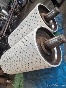
Do not confuse a guide idler with a drive pulley, tail pulley, or bend pulley. Those pulleys transmit power or change belt direction. The guide idler only steers and supports. It may be mounted on a conveyor bracket that allows tilt adjustment of about 1.5° to 2° in the direction of belt travel, which helps return the belt to centre.
What a Buyer Should Check
- Belt width and trough angle – these set the roller length and mounting position.
- Roller diameter and shaft size – do not assume a fixed shaft diameter from belt width alone.
- Bearing type and sealing – dusty or wet conditions may need better sealing.
- Surface form – rubber or ceramic may help grip, while steel is simpler.
- Mounting bracket – confirm hole spacing and adjustment range.
- Compatibility – the guide idler should work with the existing conveyor belt and idler roller frames, not replace them.
Ask for the drawing, because a guide idler is not a one-size-fits-all item. A small change in belt width or trough angle can change the roller length and the bracket position. The goal is a smooth-running belt with less edge wear and fewer spillage problems.