What Pulley Machining Involves
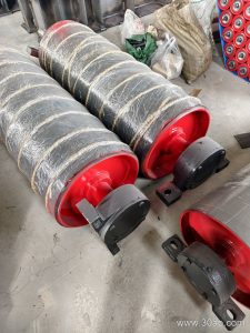
Pulley machining is the process of turning, boring, facing, and finishing a conveyor pulley so it runs true on a belt conveyor. In a quarry, coal preparation plant, or cement clinker line, a poorly machined pulley will cause belt mistracking, edge damage, and premature bearing failure. The work covers the shell, end discs, hub, and shaft seat. It also includes the preparation of the surface for lagging, whether that is plain steel, cold-bonded rubber, or hot-vulcanized diamond grooving.
The product is often called a conveyor pulley, and the machining step is what turns a welded cylinder into a balanced, concentric component. A pulley that is not machined properly may look acceptable on the bench but will vibrate once the conveyor belt is tensioned.
How a Machined Pulley Is Built
A typical build starts with a rolled steel shell, two end discs, and a hub or shaft assembly. After welding, the pulley goes to a lathe or boring mill. The machinist faces the end discs, bores the hub, and turns the shaft seat to the required fit. For larger units, the shell may be machined in sections before final assembly.
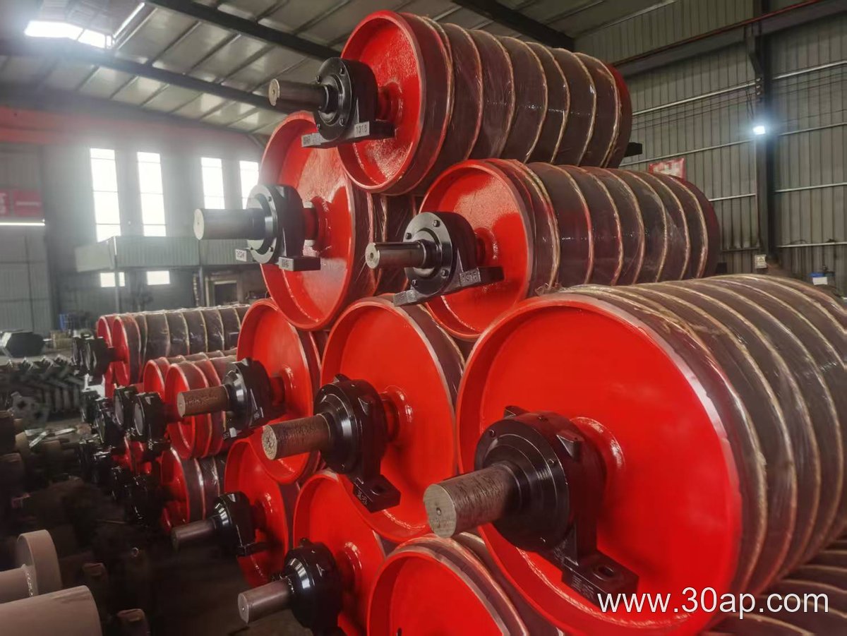
Common shell diameters include Ø200, Ø315, Ø500, Ø800, Ø1000, and Ø1250 mm. These are reference values, not fixed rules. The diameter is selected together with the belt width, the duty, and the wrap angle. A B800 belt might run on a Ø500 mm pulley in one plant and a larger diameter in another, depending on the design.
Shaft diameters are also machined to specific tolerances. Common shaft sizes include Ø50, Ø80, Ø100, Ø140, and Ø200 mm. The shaft diameter is determined by torque and load, not by belt width alone. A buyer should never assume that a B1200 belt automatically needs a Ø140 mm shaft.
Surface Forms and Lagging
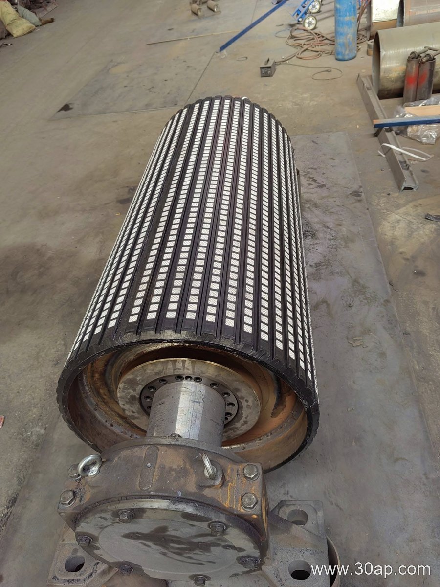
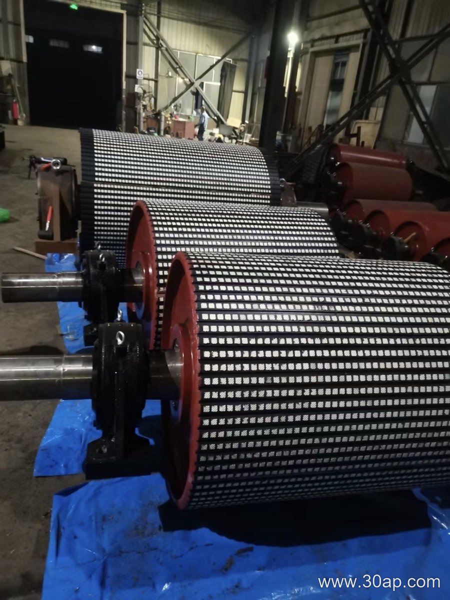
The machined surface may be left plain or prepared for lagging. Lagging improves grip and protects the shell. Typical surface forms include plain, cold-bonded rubber, hot-vulcanized rubber, diamond grooving, herringbone grooving, and ceramic lagging. Lagging thickness is often 8, 10, 12, 15, or 20 mm.
- Plain surface: used where grip is not critical or where a snub pulley is needed.
- Diamond grooving: helps water and fines escape in wet or dusty conditions.
- Herringbone grooving: provides directional traction and self-cleaning.
- Ceramic lagging: offers high wear resistance in abrasive ore handling.
For a tail pulley or bend pulley, the surface choice is different from a drive pulley. A drive pulley needs maximum grip, while a bend pulley mainly changes belt direction. Mixing these roles leads to poor performance.
Where Pulley Machining Matters Most
In a sand and gravel plant, a head pulley that is not machined concentrically will throw the belt off track. In a coal handling system, a tail pulley with a rough surface can wear the conveyor belt edges. In a power plant or steel mill, a machined pulley helps maintain belt tension and reduces the load on the conveyor bracket and idler roller assemblies.
Other industries that rely on accurate pulley machining include limestone mines, iron ore concentrators, copper mines, tunnel muck removal, fertilizer granulation, and grain silos. In each case, the pulley works with the conveyor belt and the supporting conveyor pulley frame.
Specification Examples and Combinations
The table below shows common reference combinations. They are examples only, not mandatory matches.
| Belt Width | Typical Shell Diameter | Typical Face Width | Common Shaft Diameter |
|---|---|---|---|
| B400 | Ø200–Ø315 | ≈500 mm | Ø50–Ø70 |
| B650 | Ø315–Ø500 | ≈750 mm | Ø70–Ø90 |
| B800 | Ø400–Ø630 | ≈950 mm | Ø80–Ø100 |
| B1000 | Ø500–Ø800 | ≈1150 mm | Ø100–Ø120 |
| B1200 | Ø630–Ø1000 | ≈1400 mm | Ø120–Ø160 |
| B1400 | Ø800–Ø1250 | ≈1600 mm | Ø140–Ø180 |
| B1600 | Ø1000–Ø1400 | ≈1800 mm | Ø160–Ø200 |
Note that face width is usually larger than belt width. A B1200 pulley might have a face width around 1400 mm. A B800 pulley might be around 950 mm. These are approximate references, not universal specifications.
What a Buyer Should Check
Before ordering pulley machining, confirm the belt width, the pulley type (drive, tail, bend, or snub), the required diameter, the shaft size, and the lagging preference. Ask for the balancing grade, the runout tolerance, and the surface finish. If the pulley will be used in a dusty or wet environment, specify the lagging pattern and thickness. Also check that the conveyor bracket and idler roller spacing match the pulley face width.
Do not assume that one belt width can only match one pulley diameter. The same B1000 belt may run on different pulleys at the head, tail, and bend positions. The machining must follow the actual load and the conveyor layout, not a fixed table.