Preparing the Conveyor Belt Installation
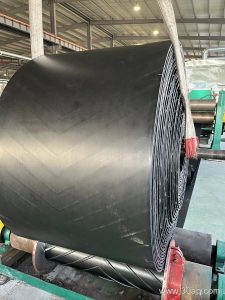
On a general manufacturing line, a conveyor belt is only as reliable as its installation. Before the belt arrives, verify the structure: pulleys must be level and square, idlers must turn freely, and the take-up has enough travel. Check that the belt width matches the pulley face and that the splice direction is correct for the intended travel. Clean the area and stage the belt on a mandrel or stand to avoid twisting or dragging.
Mounting the Conveyor Belt Correctly
Mounting begins by threading the belt through the frame without forcing it over pulley edges. Use a come-along or clamp to pull the belt evenly; never pull on the cover rubber alone. For a fabric-carcass belt, keep the pull aligned with the belt centerline. Once the ends meet, clamp both sides, square the ends, and prepare the splice according to the belt manufacturer’s instructions. After splicing, tension the belt gradually using the take-up, watching for any sign of edge damage.
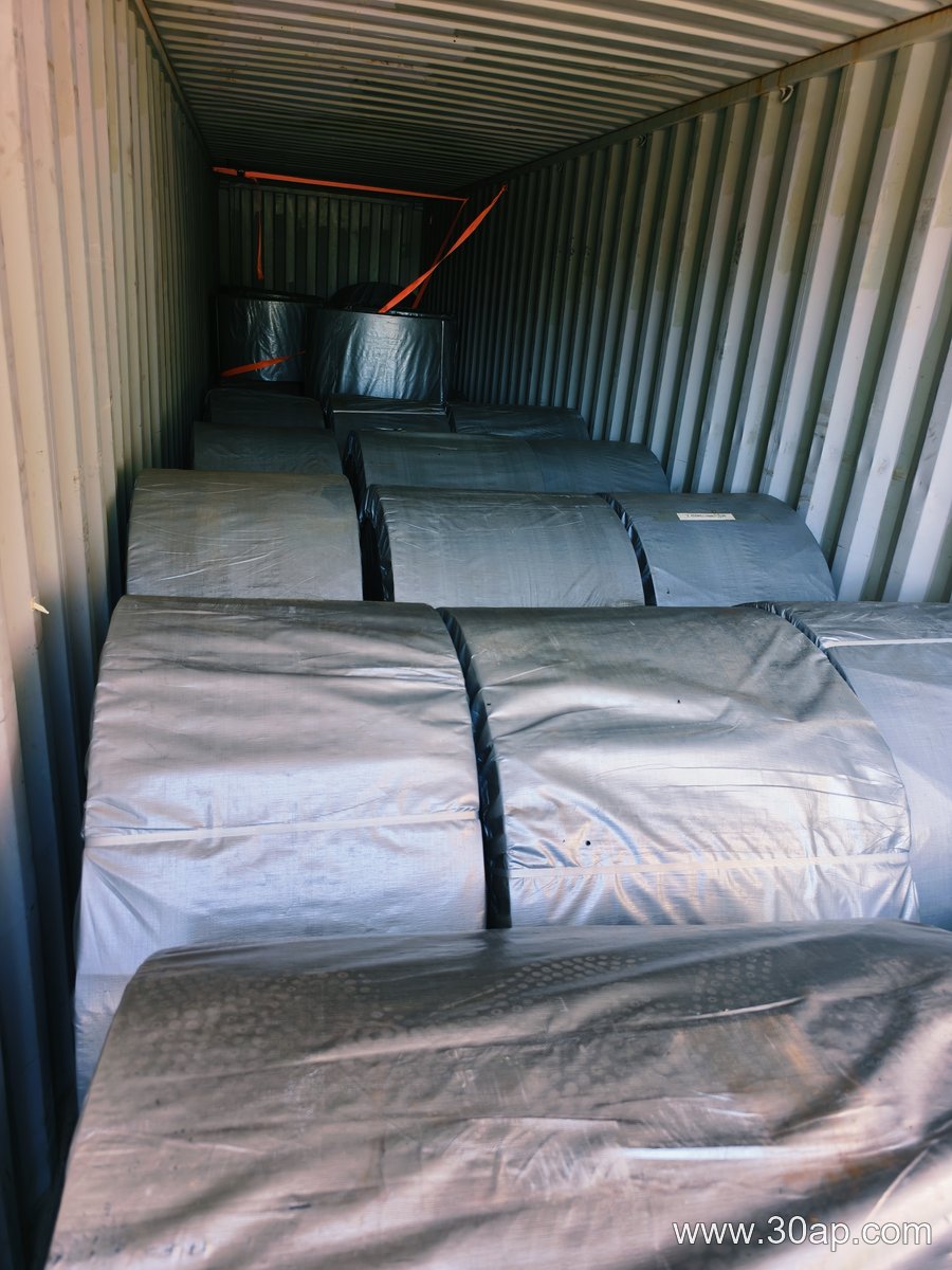
Aligning the Conveyor Belt for Smooth Tracking
Alignment is the most common source of premature belt wear. Start by checking that all pulleys and idlers are square to the belt centerline. Run the belt slowly and observe tracking at the head and tail. Adjust idlers in small increments—no more than a few degrees—and avoid over-correcting. If the belt drifts consistently to one side, inspect the structure for a twisted frame or a seized idler. A properly aligned conveyor belt will run centered without edge contact.
Commissioning Checks After Installation
Commissioning confirms that the conveyor belt and system work together. Run the empty belt for several minutes and check for unusual noise, rubbing, or belt wander. Then load the belt gradually, watching for spillage or mistracking under load. Verify that the take-up maintains tension and that the belt does not slip on the drive pulley. Record baseline observations for future maintenance. These steps help ensure the conveyor belt delivers reliable service on the manufacturing line.
How Does an Idler Roller Resist Abrasion in a General Manufacturing Line?
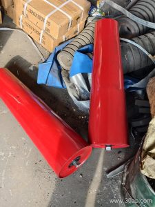
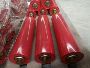
On a general manufacturing line, an idler roller often faces constant abrasion from the belt and conveyed material. Fine particles, repeated contact, and sliding friction can wear down the roller surface and shorten service life. Abrasion resistance is therefore a key performance capability for any idler roller expected to run continuously.
To assess abrasion resistance, consider this quick checklist:
- Shell material: Hardened steel, polymer, or rubber lagging offer different levels of wear protection.
- Surface hardness: Higher hardness generally improves resistance to scratching and gouging.
- Bearing sealing: Effective seals keep abrasive dust out of the bearing cavity.
- Load and speed: Higher loads and speeds accelerate abrasive wear.
- Operating environment: Moisture and chemical exposure can soften or degrade the shell.
How Abrasion Resistance Is Achieved
An idler roller resists abrasion through a combination of material choice and design. For example, a wear-resistant idler roller may use a thick-walled steel shell with a hardened outer surface. In dusty areas, a sealed idler roller prevents grit from entering the bearing, which reduces internal abrasion. Polymer rollers, such as those made from UHMWPE, can offer low friction and good sliding wear resistance, though they may be limited by temperature or load. The table below summarizes common approaches, but actual performance depends on the specific application.
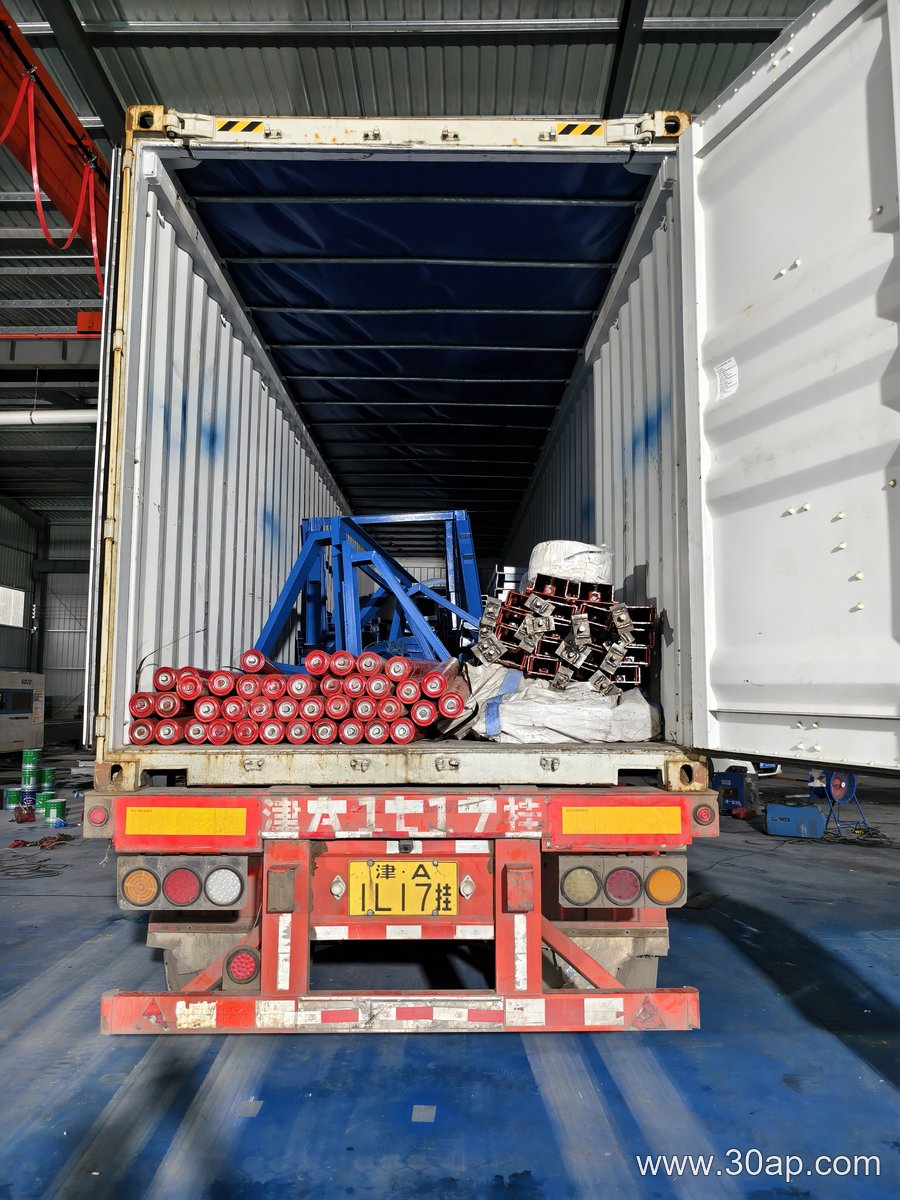
- Hardened steel shell: Good for heavy loads and coarse particles; may corrode without coating.
- Rubber lagging: Cushions impact and improves grip; can wear faster under high slip.
- Polymer shell: Lightweight and corrosion-resistant; not ideal for hot or very heavy duty.
In a hypothetical manufacturing line handling abrasive powders, a wear-resistant idler roller with sealed bearings might last significantly longer than a standard roller. However, no single solution fits all. Always match the roller’s abrasion resistance to the actual material, speed, and maintenance practices.
Practical Tips for Extending Idler Roller Life
- Inspect rollers regularly for flat spots or exposed bearings.
- Keep the belt aligned to avoid edge loading.
- Choose a sealed idler roller in dusty or dirty environments.
- Consider a belt conveyor guide idler to reduce belt wander and uneven wear.
By focusing on abrasion resistance, you can improve idler roller reliability and reduce unplanned downtime on your manufacturing line.
Conveyor Pulley Materials: What the Steel and Rubber Actually Do
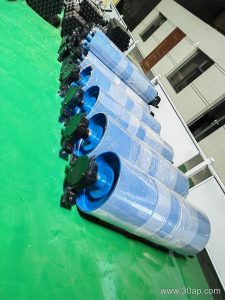
A common assumption is that any steel drum with a shaft will survive a quarry conveyor. In practice, a conveyor pulley is a loaded rotating beam, and its materials decide whether it resists abrasion, fatigue and corrosion or fails early. In a dusty quarry, airborne grit and fines work into every gap, so material choices at the shell, hub and lagging matter as much as dimensions.
Shell and Hub Construction Materials
The shell is usually carbon steel tube or rolled plate. Common grades include structural steels such as S235 or S355, or equivalent ASTM grades. Higher-strength steel allows a thinner shell for the same load, but thinner walls reduce stiffness and increase deflection risk. Weld quality becomes critical, since a conveyor pulley relies on continuous welds between shell, end discs and hub.
- Mild carbon steel: economical, weldable, adequate for moderate duty; lower fatigue resistance.
- Higher-strength carbon steel: handles higher tension with less wall thickness; needs controlled welding.
- Stainless or coated steel: resists corrosion in wet or acidic dust; higher cost and different wear behavior.
Lagging Materials and Their Trade-offs
Lagging is the outer contact layer. Rubber lagging grips the belt and cushions impact but can tear in highly abrasive grit. Ceramic lagging embeds wear-resistant tiles in rubber, improving traction and abrasion resistance, though it costs more and can damage a belt if tiles protrude. Plain steel or grooved steel drums suit lower-tension, non-slip duties but offer less grip when wet.
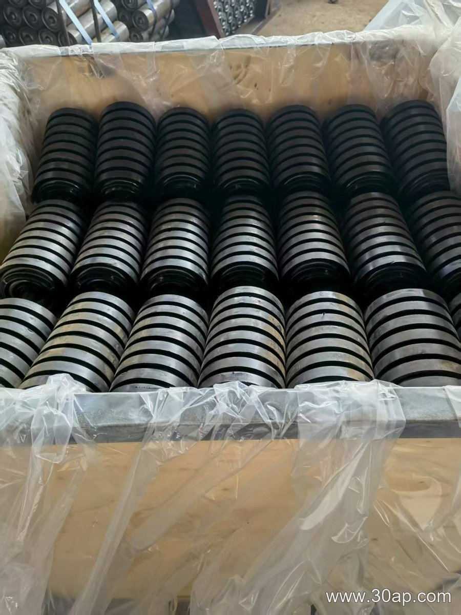
Quarry Dust and Material Selection
In a dusty quarry, fine silica or limestone dust acts as a grinding paste. A conveyor pulley with rubber lagging may polish and lose grip; ceramic lagging often performs better where slip is unacceptable. Sealing and shaft material also matter—grit reaching the bearing area accelerates wear regardless of shell grade.
Hypothetical example: a 500 mm diameter head pulley on a 1,000 mm belt might use an S355 shell with ceramic lagging, while a low-tension tail pulley could use S235 steel with plain lagging. These values illustrate trade-offs, not fixed rules. Selection should follow the actual belt tension, duty and environment.
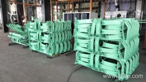
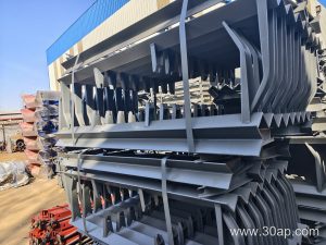
When specifying a conveyor bracket for a cement plant, engineers often face a trade-off: a stiff, welded bracket resists vibration but offers no field adjustment, while an adjustable bracket simplifies alignment but can loosen under impact. To illustrate, consider a hypothetical project: a 1,200 mm wide belt carrying clinker at 150 t/h, with a troughing angle of 35°. The goal is to select a bracket that supports idlers without excessive deflection.
Assumptions and Design Loads
Assume the bracket must carry a 100 kg idler assembly plus 50 kg of material load per idler station. The belt speed is 2.5 m/s, and the bracket spans 400 mm between mounting holes. We treat the load as static for stiffness check, ignoring dynamic factors for simplicity. The bracket material is mild steel with a yield strength of 250 MPa. Deflection limit is set to L/360, or about 1.1 mm.
Comparing Two Conveyor Bracket Configurations
Option A is a fixed, welded bracket with a 6 mm thick mounting plate and two gussets. Option B is an adjustable bracket with slotted holes and a 8 mm plate. A simple beam calculation for a cantilever of length 150 mm (effective) gives:
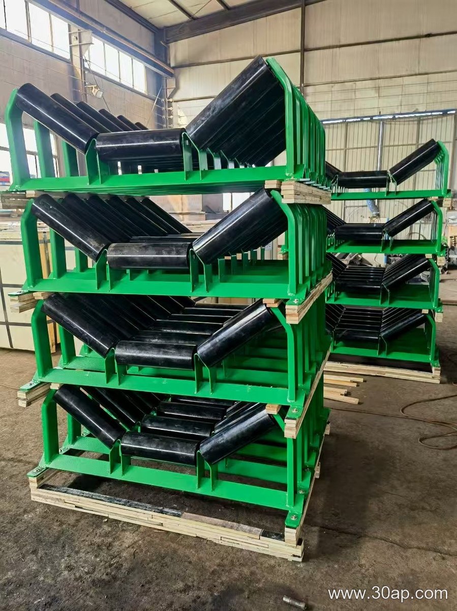
- Option A: moment of inertia I = 1.8×10⁵ mm⁴; deflection ≈ 0.7 mm.
- Option B: I = 3.2×10⁵ mm⁴ due to thicker plate; deflection ≈ 0.4 mm, but slot slip may add 0.3 mm under vibration.
Both meet the deflection limit, but Option A is stiffer and cheaper; Option B allows easier alignment after belt tracking issues. In a cement plant, dust and heat can cause thermal expansion, making adjustability valuable.
Decision and Practical Notes
For this hypothetical case, we choose Option B with added lock washers and periodic torque checks. The conveyor bracket must be inspected for looseness every 500 hours. Note that actual loads vary with material bulk density and idler spacing; always verify with a qualified engineer. This example is illustrative, not a universal specification.