Where the Conveyor Impact Idler Earns Its Place
Material does not arrive on a belt gently. At every transfer chute, crusher discharge, and loading point, lumps of rock, clinker, or ore drop onto the conveyor belt with force that a standard carrying idler is not designed to absorb. The conveyor impact idler sits directly under that landing zone, and its job is simple to state but demanding to perform: take the hit, spread it, and keep the belt running without damage.
In a quarry, limestone mine, or sand and gravel line, the drop height at the primary crusher outlet can be considerable. The same applies in a coal handling system feeding a power plant bunker, or a cement plant receiving raw material from a tipper. In each case, the impact idler is the first line of defence for the belt carcass.
How an Impact Idler Is Built
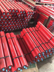
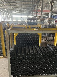
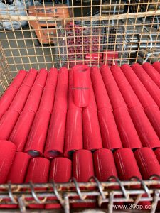
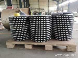
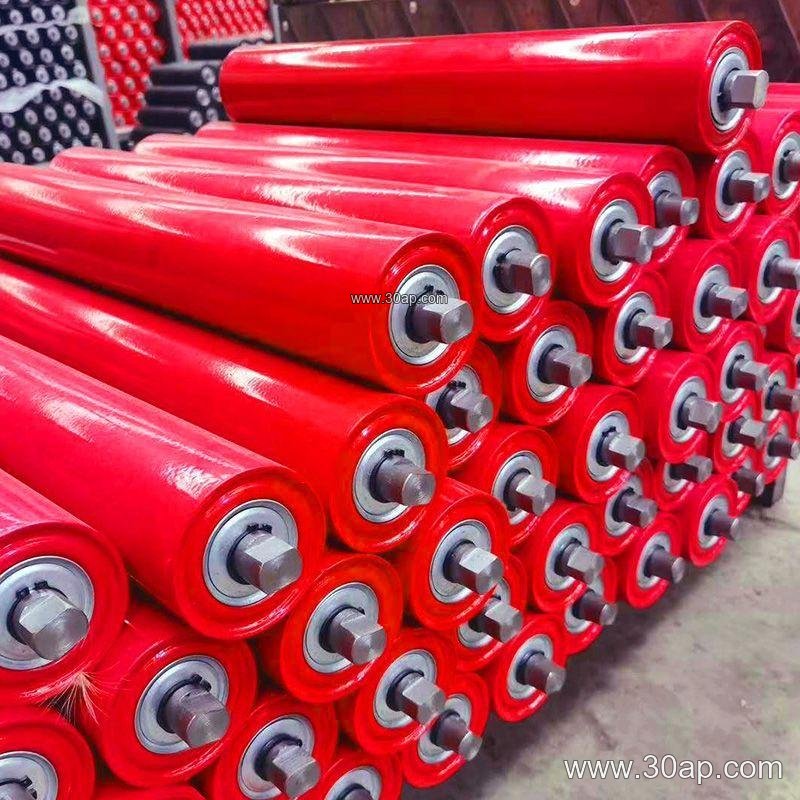
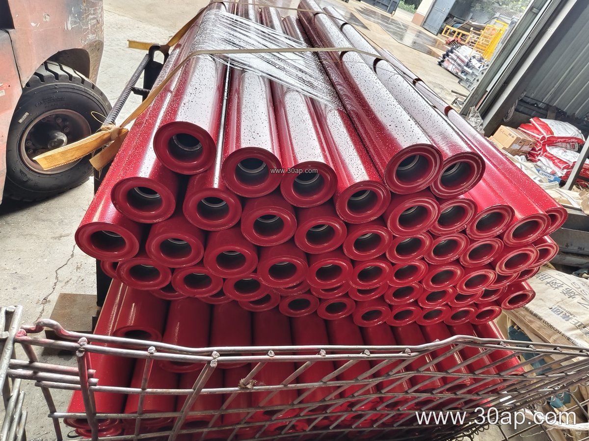
An impact idler roller differs from a conventional carrying idler mainly at the surface. Instead of a bare steel shell, the roller carries a series of rubber rings or discs, sometimes a continuous rubber sleeve, mounted on a steel body. The rubber deforms under the falling material, lengthening the deceleration distance and reducing the peak force transmitted to the belt and frame.
Inside, the roller uses the same basic arrangement as other idlers: a shaft, bearing housings, and sealed bearings. Common bearing sizes in this family include 6205, 6305, 6306, and 6308, matched to the shaft and load rather than to a single roller diameter. Roller diameters are usually chosen from ranges such as Ø89, Ø108, Ø127, Ø133, Ø159, and Ø178 mm, with the larger sizes preferred where lumps are heavy and drop heights are significant.
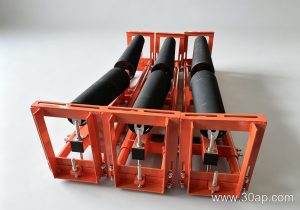
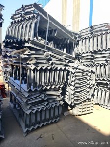
The frame that holds the rollers is equally important. A buffer station is normally built as a close-spaced group of impact rollers, often in a three-roller trough arrangement with a 30 or 35 degree trough angle, so that the belt is supported continuously through the impact zone. The spacing between rollers in this group is tighter than in an ordinary carrying run, which is what prevents the belt from sagging between supports under a heavy strike.
Impact Idlers Versus Ordinary Carrying Idlers
A standard troughing idler with a steel shell is efficient on the steady carrying run, but it offers little cushioning. When a 300 mm lump lands on it, the belt takes almost the full shock. A rubber-ring impact idler absorbs part of that energy and spreads the rest across several rollers.
This is also where the belt specification matters. A heavy-duty mining conveyor belt or a high abrasion resistant conveyor belt can tolerate more punishment, but no carcass enjoys repeated point loads. Fabric core belts such as EP conveyor belt and NN conveyor belt grades benefit from a well-designed buffer station, and steel cord conveyor belt installations handling ore at high tonnage usually specify impact rollers as a matter of course. The buffer zone also protects the splice, which is often the weakest point on a conveyor belt.
Note that the impact idler is not a substitute for a transition idler or a training idler. Each has a distinct role: transition idlers ease the belt from pulley curvature into the trough, training idlers correct misalignment, and impact idlers absorb falling energy. They are complementary, not interchangeable.
Typical Service Conditions
Impact idlers appear wherever a conveyor receives material rather than merely carrying it. Frequent locations include:
- Crusher discharge points in stone crushing and ore handling plants
- Transfer towers on overland conveyors in iron ore and copper ore operations
- Loading points at port terminals and ship loading systems
- Raw material receiving stations at cement plants and power plant coal yards
- Aggregate conveyor belt lines in sand and gravel plants
In underground mining conveyor belt systems, space is tight and maintenance access is limited, so impact stations are often specified with sealed bearings and wear-resistant rubber rings to extend service intervals.
What to Check Before Ordering
Buyers should start with the belt width and the trough configuration, because roller length follows the belt width, trough angle, and roller group form. For a three-roller trough, common roller lengths run roughly 200 mm at B500, 250 mm at B650, 315 mm at B800, 380 mm at B1000, 465 mm at B1200, 530 mm at B1400, 600 mm at B1600, 670 mm at B1800, and 750 mm at B2000. These are reference examples, not fixed pairings, and side rollers may differ from the centre roller.
Also confirm the drop height, the maximum lump size, and the material density. Heavier lumps and greater fall heights call for larger roller diameters, thicker rubber rings, and closer roller spacing. The conveyor bracket and frame must be rated for the same dynamic load, since a strong roller on a light frame simply moves the problem.
Finally, ask about the bearing seal and the rubber compound. Dust, grit, and moisture attack bearings quickly in a quarry or coal yard, and oil or chemical exposure may call for a different rubber grade. A well-matched impact station, reviewed together with the conveyor pulley arrangement and belt specification, will keep the receiving end of the line running quietly for years. For related equipment such as conveyor idler rollers and conveyor pulleys, buyers can review options at gyconveyorbelt.com before finalising the order.