What an Adjustable Conveyor Bracket Does
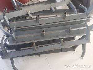
An adjustable conveyor bracket is a frame component that carries idler rollers and lets maintenance crews change the troughing angle of the belt line without cutting or re-welding the structure. Instead of a welded, single-angle frame, the bracket uses slotted or pivoting mounting points, so the same support position can run at a shallow profile for one duty and a deeper profile for another. In a quarry or a cement plant, that flexibility often means fewer spare frame variants in the warehouse and faster changeover when a conveyor section is re-purposed.
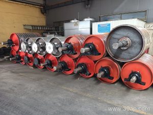
The product is also called an adjustable idler bracket or adjustable roller support frame. It is not a drive pulley bracket, not a tail pulley bracket, and not a bend pulley bracket; those components hold rotating pulleys at the head, tail and curve of the conveyor, and they serve a different structural purpose. An adjustable bracket belongs to the idler side of the machine, together with the conveyor bracket family that includes troughing, transition, return and self-aligning supports.
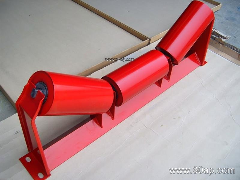
Construction and Adjustment Method
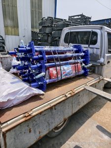
Most units are fabricated from angle steel, channel steel or folded steel plate. Two features matter most to a buyer: the pivot or slot that sets the wing angle, and the locking detail that holds the setting under vibration. Common designs use a bolted slotted arc, a hinged wing plate with a clamp bolt, or a set of index holes. A scale or stamped marks on the frame help crews repeat a known angle.
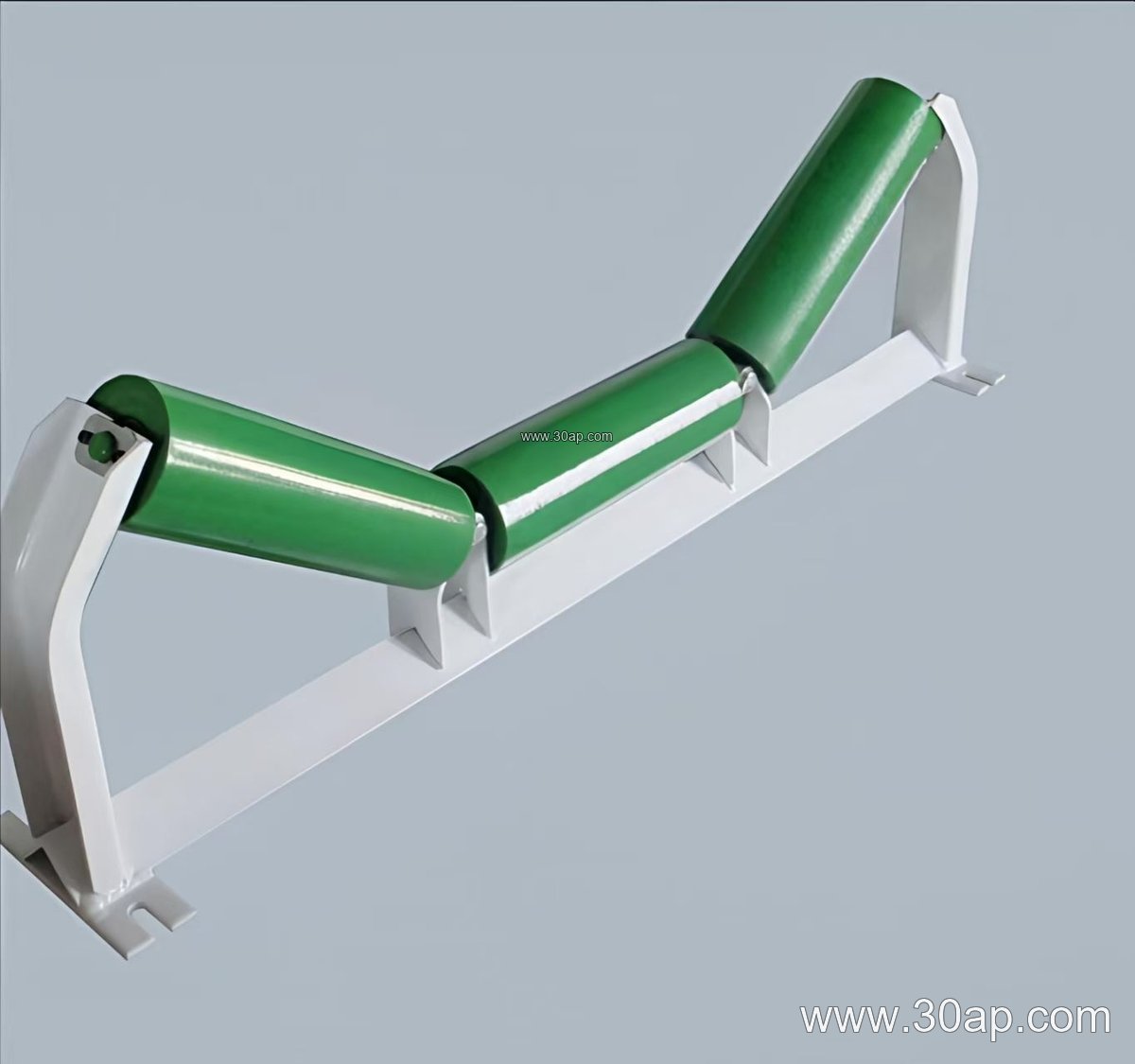
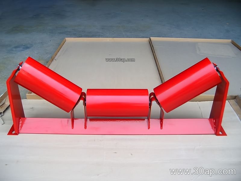
In a typical troughing position, the bracket supports the centre roller and two wing rollers. The adjustable version allows the wings to move between common trough angles such as 20, 30, 35 and 45 degrees. Some forward-leaning designs add a small tilt of roughly 1.5 to 2 degrees to help belt tracking, though that is a separate feature from the trough angle adjustment itself. Installation hole spacing and crossbeam length are not fixed numbers; they follow the belt width, the chosen trough angle and the roller diameter, so they should be confirmed against the conveyor drawing.
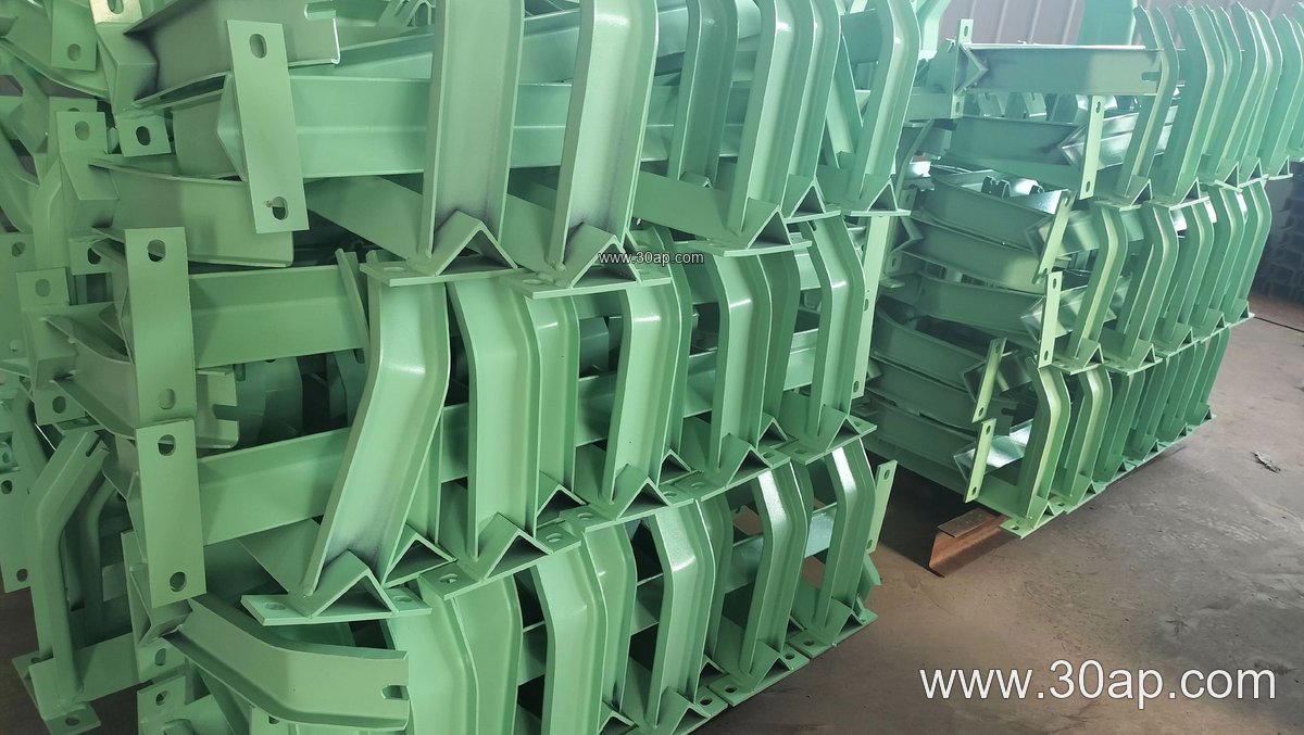
- Frame material: angle, channel or folded plate, painted or galvanised as specified
- Adjustment range: commonly 20 to 45 degrees, with locking bolts or index holes
- Mounting: bolted to the conveyor stringer, with slots to absorb minor alignment error
- Wear points: pivot pins, clamp bolts and slot edges, which should be checked at service intervals
Where It Fits on the Line
These brackets are used where the belt profile needs to change or where one frame design must cover several positions. In a coal washing plant, a transition zone between a flat tail section and a fully troughed run is a natural place for an adjustable support. In a limestone crushing and screening line, the same bracket may be set shallow at a transfer point and deeper along the main haul, which helps keep a heavy abrasion resistant conveyor belt centred on its rollers. Port and ship loading conveyors also benefit when the trough angle is tuned to suit different bulk materials without a structural rebuild.
In a power plant coal yard, crews often pair adjustable frames with a flame retardant conveyor belt and standard idler roller sets, then fine-tune the wing angle after the belt has been tensioned and run in. In an iron ore or copper ore operation, a steeper trough may be selected to contain a fast-moving load, while a gentler angle is kept near the loading point to reduce edge stress on a steel cord conveyor belt or a multi-ply fabric core belt.
Common Reference Combinations
The table below shows typical pairings that appear in project drawings. They are reference examples, not mandatory matches, and a belt width does not dictate a single trough angle or roller diameter.
| Belt width | Trough angle | Roller diameter | Typical position |
|---|---|---|---|
| B650 | 30 degrees | Ø89 | Small aggregate or sand line |
| B800 | 35 degrees | Ø108 | Cement plant transfer |
| B1000 | 35 degrees | Ø133 | Coal yard main haul |
| B1200 | 45 degrees | Ø133 | Iron ore or heavy bulk duty |
| B1400 | 35 degrees | Ø159 | Port loading conveyor |
| B1600 | 45 degrees | Ø194 | High-capacity primary haul |
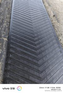
Wider frames up to B1800, B2000 and B2200 exist for large installations, and the wing geometry is designed accordingly. On a chevron conveyor belt or a corrugated sidewall belt, the roller set and bracket clearance must be checked so that cleats or sidewalls do not contact the frame.
Buyer Checklist
- Confirm belt width, required trough angle range and roller diameter before ordering.
- Ask for the mounting hole spacing and crossbeam length that match your stringer layout.
- Check that the locking method suits the vibration level of the position.
- Decide on surface treatment: painted, galvanised or another specified finish.
- Match the bracket material to the environment, especially in wet or dusty service.
- Keep pivot pins and clamp bolts on the inspection route; a loose lock can change belt shape gradually.
Used correctly, an adjustable conveyor bracket gives maintenance teams a practical tuning point between the belt, the idler roller and the supporting structure, and it reduces the number of dedicated frames a plant must stock for different trough profiles.